


VENDOMA DVR
t
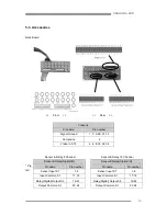
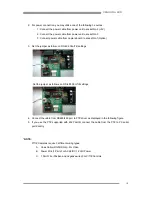
7-2. Rear View
1. AC Power Cooling fan – This fan also removes the excessive heat generated in the system and
enhances the system’s stability
2. Sensor & Relay I/O connectors – This is the sensor and relay-out port for systems that have a
BNC back panel installed. Systems that have a pigtail type connector (also called a Dongle)
installed do not need this type of sensor.
3. Camera input connectors – This is the camera input for systems that have a BNC back panel
installed. Systems that have a pigtail type connector (also called a Dongle) installed do not need
this type of In/Out port.
4. Composite output connector – This is the TV-out port for analog monitoring found on
CAP2X6016 and CAP12016 boards. On other types of boards, the TV-out port is located on the
capture board (see part #6 above).
5. Live video composite output connector – This is the TV-out port for analog monitoring when
you use a Vendoma Live board. In this case, the analog views from TV-out are the same as in
multi-view on Vendoma Main.
6. Capture board composite output connector – This is the TV-out port for analog monitoring
when you use a capture card. In this case, camera views are attained one by one by switching
all of the channels being viewed on Vendoma Main.
7. AC power switch – This power switch is for turning on the unit. You should not use this switch
for turning off the system. This switch is for emergency purposes only.
8. AC power socket – This is the power socket. Prior to inserting the power cord, you should take
care to notice the allowable voltage.
9. PS/2 mouse connector
10. PS/2 keyboard connector
11. USB connectors
12. LPT, COM1, COM2 connectors – These are the parallel ports for connecting a printer, an
RS485, an RS422, or other serial device.
13. Game, Sound connectors – These are the game ports and sound ports for the speakers.
28


