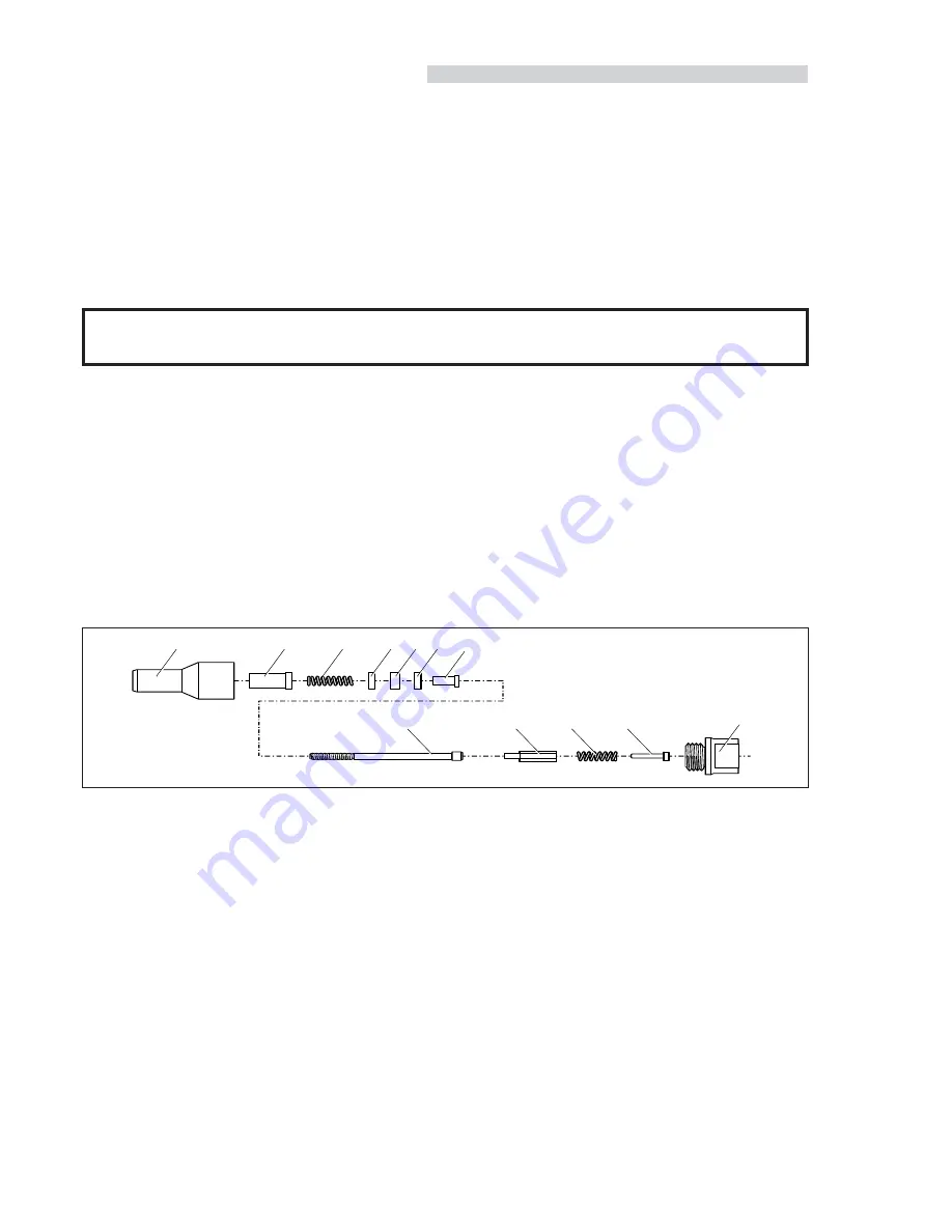
Nose assemblies are specifically designed for each size and type of insert used with the 07557 type of tooling. If you have purchased
a complete tool, it will already be fitted with the correct nose assembly for your insert.
It is essential that the correct nose assembly is fitted prior to operating the tool. By knowing your original complete tool part number
or the details of the insert to be placed, you will be able to order a new complete nose assembly using the selection tables pages 4 and 5.
FITTING INSTRUCTIONS
I M P O R T A N T
The air supply must be disconnected when fitting or removing nose assemblies unless specifically instructed otherwise.
Before fitting the nose equipment, ensure the clutch on the tool is set to the correct torque for the insert being placed.(Torque values
are quoted on pages 4 & 5.)
Where applicable, insert sleeve 8 and thrust spring 9 into nose housing 2.
Coat thrust washers 3 and thrust bearing 4 with high pressure grease (eg. Shell Alvania E.P.I.) and locate them in the order shown below
into the nose housing 2.
Where applicable, fit spacer 5 through thrust washers and thrust bearings.
Insert drive screw 1 through the above assembly.
Fit drive shaft 6 into the hexagon hole in the drive screw head.
Insert stop 11 and spring 10 into the front of the base tool.
Screw adaptor 7 into clutch housing of the base tool (left hand thread).
Offer up the nose assembly to the adaptor. It will be necessary to rotate the drive screw by hand to line up the hexagon on the drive shaft
6 with the hexagonal hole in the front jaw of the base tool.
Screw the nose housing 2 onto the adaptor 7 and tighten with a spanner (left hand thread).
8
N
O S E A S S E M B L I E S
2
7
10
11
8
9
4
3
3
5
1
6
■
■
■
■
■
■
■
■
■
SERVICING INSTRUCTIONS
Nose assemblies should be serviced at weekly intervals.
Remove the complete nose assembly using the reverse procedure to the ‘Fitting Instructions’.
Any worn or damaged part should be replaced by a new part.
Particularly check wear on drivescrew, thrust washers and thrust bearing.
Check springs are not distorted.
Check the clutch torque setting (see page 4 & 5 for details)
Lubricate thrust washers and thrust bearings with high pressure grease (eg Shell Avania E.P.I.)
Lubricate the clutch with high pressure grease.
Assemble according to fitting instructions.
■
■
■
■
■
■
■
■
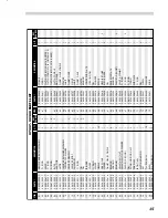
NOSE ASSEMBLY COMPONENTS
The table opposite lists all nose assemblies available. Each nose assembly represents a unique assembly of components which can be
ordered individually. Components numbers refer to the illustration above. We recommend some stock as items will need regular
replacement. Read the nose assemblies servicing instructions above carefully. All nose assemblies also include spring 10 part number
07430-08282 and stop 11 part number 07430-08203.


