22
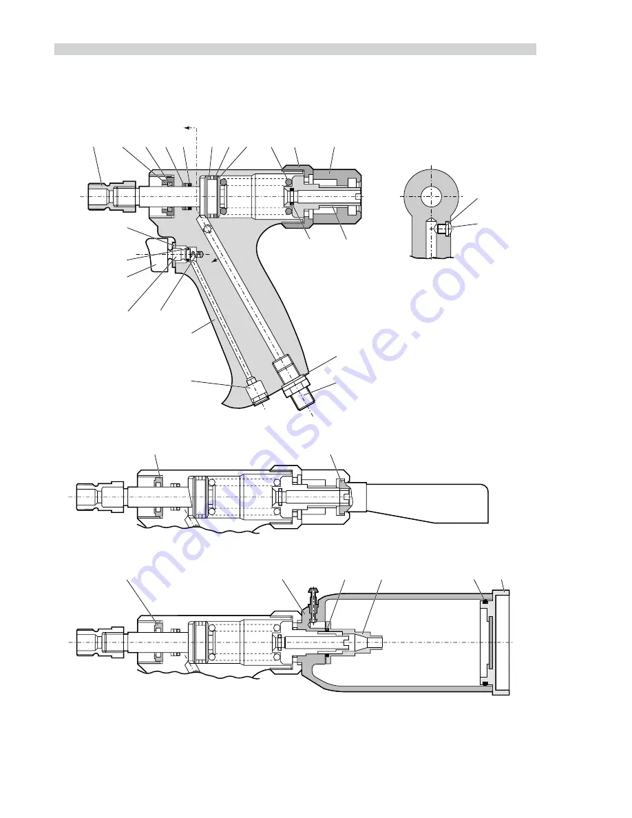
GENERAL ASSEMBLY OF BASE TOOLS (MODELS 07241-00200/07242-00200/07245-00200)
7245
27
28
29
32
30
31
7241
25
26
7242
SECTION 'A'-'A'
'A'
1
2
3
4
5
6
7
8
9
10
11
12
13
21
20
19
18
17
16
15
14
24
23
Page 1: ...Instruction Manual 0724 type 07241 07242 07243 07244 07245 Hydro Pneumatic Power Tool Pass onto user to read and keep for reference...
Page 2: ...ar 80 lbf in2 9 litres 32 ft3 STROKE 07241 4 5 Minimum 18 54 mm 73 in 07242 3 Minimum 15 9 mm 63 in PULL FORCE 5 5 bar 80 lbf in2 10 20 kN 2250 lbf CYCLE TIME Approximately 1 second NOISE LEVEL 70 3 d...
Page 3: ...omponents 14 07242 07243 Fitting Servicing Components 15 16 Regular Servicing 17 18 Service Kit 18 Maintenance Tool and Intensifier 19 21 Tool General Assembly Parts Lists 22 23 Intensifier General As...
Page 4: ...E UNDERTAKEN ONLY BY PERSONNEL TRAINED IN AVDEL PROCEDURES DO NOT DISMANTLE THIS TOOL MACHINE WITHOUT PRIOR REFERENCE TO THE MAINTENANCE INSTRUCTIONS CONTACT AVDEL WITH YOUR TRAINING REQUIREMENTS THE...
Page 5: ...THE APERTURE IS FACING AWAY FROM THE OPERATOR AND OTHER PERSON S WORKING IN THE VICINITY THE INTENSIFIER RETAINING RING MUST BE ASSEMBLED WITH THE RETAINING PLATE SPECIFIED WHEN USING THE TOOL THE WEA...
Page 6: ...07241 00075 07241 00066 07241 00076 07241 00062 07241 00072 07241 00067 07241 00077 07241 00058 07241 00008 07241 00015 07241 00027 07241 00003 07241 00005 07241 00028 07241 00010 07241 00012 07241 0...
Page 7: ...l Alloy Al Alloy AVEX Snap head 120 csk AVINOX BE11 BE61 BULBEX AVIBULB Low profile 1 8 5 32 3 16 1 8 5 32 3 16 5 32 3 16 1 8 5 32 3 16 07241 00001 07241 00001 07241 00001 07241 00001 07241 00001 0724...
Page 8: ...32 3 16 07242 00004 07242 00005 07242 00005 07242 00006 07242 00006 07242 00006 07242 00064 07242 00065 07242 00074 07242 00075 07242 00005 07242 00006 07242 00014 07242 00017 07242 00024 07242 00015...
Page 9: ...6 07243 00006 07243 00006 07243 00064 07243 00065 07243 00074 07243 00075 07243 00005 07243 00006 07243 00014 07243 00017 07243 00024 07243 00015 07243 00018 07243 00016 07243 00019 07243 00023 07243...
Page 10: ...embly for use where access is unrestricted Use the selection chart opposite to select a complete 07245 tool which will include the correct nose assembly for a selected fastener For details of Nose Ass...
Page 11: ...245 02200 07245 02400 07245 02100 07245 02200 07241 02700 07245 02300 07245 02500 07245 02300 07241 03100 07245 02600 07241 03600 07244 02200 07241 04200 07245 02200 07245 02300 07241 02700 07241 0310...
Page 12: ...at an optimum pressure of 5 5 bar We recommend the use of pressure regulators and automatic oiling filtering systems on the main air supply These should be fitted within 3 metres of the tool see diagr...
Page 13: ...en the locking ring 7 8 10 11 6 9 2 3 4 2 5 1 11 A C C E S S O R I E S CONNECTION FOR VACUUM TUBE Approximate dimensions of assembled unit are Length 125mm 4 9 Diameter 89mm 3 5 The stem catcher MUST...
Page 14: ...ed combination produces five models 07241 07244 07242 07243 and 07245 If you have purchased a complete tool it will already be fitted with the correct nose assembly for your fastener It is essential t...
Page 15: ...06 07340 00304 07340 00213 07241 03002 07241 02001 07241 03003 07241 03700 07490 04400 07340 00306 07340 00304 07340 07502 07241 03702 07241 02001 07241 03003 07241 03800 07498 01400 07340 00306 07340...
Page 16: ...08301 07340 00306 07340 00304 07340 07502 07241 03702 07241 02001 07241 03003 07241 05000 07340 07601 07340 00306 07340 00304 07340 00213 07241 02602 07241 02001 07241 02603 07241 05400 07498 09101 0...
Page 17: ...hrough the hole of body 5 not a slot Lubricate the sides of the jaw carrier assembly and insert into body 5 Lubricate rollers 8 and ENSURE that they will freely rotate in the holes of adaptor 9 If nec...
Page 18: ...03500 07345 03501 07498 04401 07346 04000 07165 00701 07340 00229 07346 04100 07165 00702 07340 00229 07346 04200 07165 00703 07498 04401 07346 04300 07165 00801 07340 00229 07346 04400 07165 00802 07...
Page 19: ...bricator is fitted on air supply If the tool is in continuous use the air hose should be disconnected from the main air supply and the tool lubricated every two to three hours Check for air leaks If d...
Page 20: ...if applied by an experienced operator HANDLING Use barrier cream or oil resistant gloves STORAGE Away from heat and oxidising agent ITEM PART N DESCRIPTION N OFF ITEM PART N DESCRIPTION N OFF 07900 00...
Page 21: ...pages 12 to 16 For total tool servicing we advise that you proceed with dismantling of sub assemblies in the order shown below The procedure is the same for all tools once the nose assembly has been...
Page 22: ...spacer 18 and retaining plate 19 Using a screwdriver carefully remove the internal retaining ring 13 Using extractor insert the male threaded end into the end cover 11 Withdraw end cover 11 Insert a l...
Page 23: ...64 and 65 to pilot valve spool 52 and insert into pilot valve body Fit new seals 62 63 and 66 to pilot valve body place top cap 51 in position and secure pilot valve assembly to the main valve body 47...
Page 24: ...22 GENERAL ASSEMBLY OF BASE TOOLS MODELS 07241 00200 07242 00200 07245 00200 7245 27 28 29 32 30 31 7241 25 26 7242 SECTION A A A A 1 2 3 4 5 6 7 8 9 10 11 12 13 22 21 20 19 18 17 16 15 14 24 23...
Page 25: ...11 07241 00206 END CAP 1 12 07245 00201 STEM CATCHER ADAPTOR 1 ITEM PART N DESCRIPTION QTY SPARES 13 07003 00029 O RING 1 1 14 07003 00142 BONDED SEAL 1 1 15 07005 00406 CONNECTOR 1 16 07005 00599 O R...
Page 26: ...64 65 66 53 61 57 56 58 59 55 54 60 48 51 66 63 47 49 68 67 INTERFACE O RINGS AND SCREWS 40 41 42 43 44 39 VIEW B VACUUM EXTRACTION 07246 00200 37 38 45 46 VIEW B 07240 00200 28 29 31 30 27 26 25 32...
Page 27: ...1 1 13 07004 00069 RETAINING RING 1 1 14 07240 00213 FOAM SILENCER 1 1 15 07240 00214 FILTER COVER 1 16 07002 00017 NUT 1 1 17 07001 00417 SCREW 1 1 18 07240 00215 SPACER 1 19 07240 00216 RETAINING PL...
Page 28: ...C 32 100 C 5 3 Relative density at 20 C 0 875 Viscosity Index 95 Pour point C 30 Open Flash point C 232 Neutralisation value mg KOH g 1 5 H Y S P I N V G 32 O I L S A F E T Y D A T A ENVIRONMENT WAST...
Page 29: ...nd replace the bleed screw and seal 23 24 Filling the intensifier unit Connect the intensifier unit to the air supply Remove screw from reservoir Fill the oil reservoir with the with the recommended p...
Page 30: ...t nylon locking ring Weak or broken nose assembly spring Replace spring Incorrect nose equipment fitted Replace as necessary Jaws will not release Dirty jaws or jaw housing Clean spent rivet stem Jaw...
Page 31: ...tive documents EN292 part 1 and part 2 ISO 8662 part 1 ISO 3744 ISO PREN792 part 14 Products mentioned and or illustrated within this publication are subject to patent design or copyright protection i...
Page 32: ...x 39 039 2873079 Email vendite acument com JAPAN Acument Japan Kabushiki Kaisha Center Minami SKY 3 1 Chigasaki Chuo Tsuzuki ku Yokohama city Kanagawa Prefecture Japan 224 0032 Tel 81 45 947 1200 Fax...