

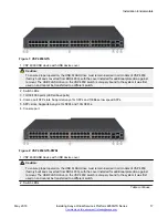


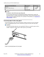


Airflow direction
Airflow direction in the VSP 4850GTS, the VSP 4850GTS DC, and the VSP 4850GTS-PWR+ is
from left to right (as viewed from the front). Cool air enters the chassis through an air inlet at the left
of the chassis, which cools the device. Warm air exits through the exhaust at the right.
Package contents
The following describes the components that are provided with each switch. If any components are
missing, contact the switch vendor.
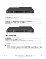
1. Avaya Virtual Services Platform 4000 4850GTS switch with one power supply installed.
2. Rack-mounting hardware that includes:
• Rack-mount brackets
• Screws to attach brackets to the switch
• Screws to attach the switch to the equipment rack
3. Rubber footpads.
4. AC power cord with an IEC 60320 C16 connector.
Note:
A power cord is not included for the A variant of the switch.
5. Documentation that includes the following:
a.
Locating the latest software and product release notes for Avaya Virtual Services
Platform 4000 Series
, NN46251-106
b.
Avaya Virtual Services Platform 4000 Series Regulatory Guide
, NN46251-105
c.
Avaya Virtual Services Platform 4000 Series 4850GTS Series Quick Install Guide
,
NN46251-302
d. The China RoHS paper
Note:
Cable trays can be provided as an option.
Installing the Avaya Virtual Services Platform 4000 on a
table or shelf
You can install a single Avaya VSP 4000 switch on any flat surface. The surface must support the
combined weight of the switch and attached cables (from 15 and 20 pounds [7 to 9 kilograms]).
Installing the Avaya VSP 4000 4850GTS Series
May 2016
Installing Avaya Virtual Services Platform 4850GTS Series
22