


3. Remove the fan module that failed by pushing the tab on the spring latch to the left and
pulling on the fan’s extraction handle.
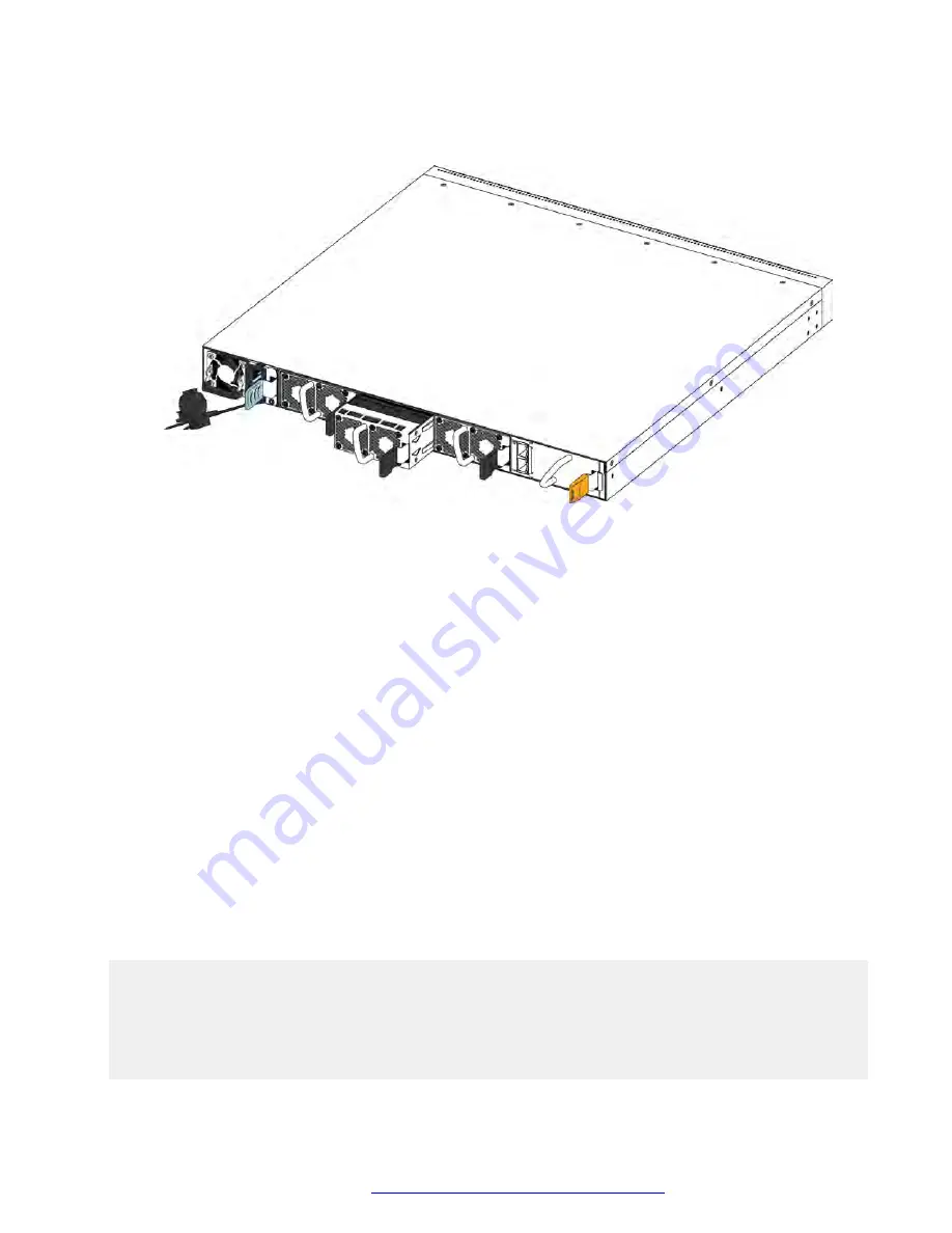
4. Insert the new fan module into the chassis.
Important:
You can hot swap fan modules while the switch is operational.
5. Verify that the fan module is fully seated in the chassis. The spring latch should engage and
return to its original position.
6. Enter the following command to check the temperature sensors inside the switch.
show sys-info temperature
Example
Check the status of the fan modules.
Note:
There are three fan modules in the VSP 7200 Series and each fan module has two fans for a
total of six fans. Each fan has its own ID and the
show sys-info fan
command reports its
status.
The Fan IDs are assigned from left to right as you face the back of the chassis. For the first fan
module on the far left, the Fan IDs are 1 and 2, the next fan module has Fan IDs 3 and 4, and
the fan module on the far right has Fan IDs 5 and 6.
VSP-7254XSQ:1>show sys-info fan
Fan Info :
Fan Id Fan Status Fan Type FanFlowType
--------------------------------------------------------
1 up regularSpeed front-back
2 up regularSpeed front-back
3 up regularSpeed front-back
4 up regularSpeed front-back
Installing the Avaya Virtual Services Platform 7200 Series
November 2016
Installing the Avaya VSP 7200 Series
34


