Avaya G250 and G250-BRI Branch Office Media Gateways w/FIPS Non-Proprietary Security Policy
Version 1.2 Wednesday, 14 December, 2005
© 2005 Avaya Inc.
May be reproduced only in its original entirety [without revision]. Page 9 of 23
CID 106595
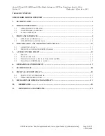
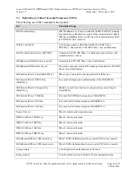
#
Interface
Qty
Logical interface definition
Comments
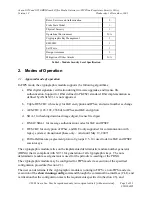
Data input/output, power output
Trunk, providing a power interface, when an
emergency state occurs:
a)
Power failure
b)
Failure to communicate with a call
controller
c)
Firmware error state
5.
Analog Trunk
4
Analog Phone Trunks.
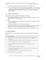
Data input/output, power input
The Trunk ceases to be a data input/output from
the module and is directly connected to Analog
Line 2, providing a power interface, when an
emergency state occurs:
a)
Power failure
b)
Failure to communicate with a call
controller
c)
Firmware error state
6.
Console
1
Control inputs, Status output
Supports cryptographic module administration.
7.
USB
1
Control inputs, Status output,
Power output
Supports cryptographic module administration for
modem dial in connection. Disabled in FIPS
Approved mode.
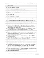
8.
Media Module
Connectors
2
Data input, data output, status
output, control input
Provide the ability to communicate using,
Serial/TDM Data, Ethernet, PCI, CPU Device
Bus, facilitates Power.
9.
AC Power
Input
1
Power Input
Provides power to the module from an external
source.
10. Ground
Connector
1
Ground
Provides power to the module from an external
source.
11. Reset Button
1
Control Input
Resets the device
12. ASB Button
1
Control Input
When pressed with the reset button, cause the
device to boot from an alternate firmware image
bank
13. System LEDs
4
Status Output
Indicates Power, Modem connection through
Console interface, CPU activity, and Alarm state.
14. LEDs on ETH
WAN
2
Status Output
Link state and activity indication on the
associated data interface
15. LEDs on ETH
LAN
2
Status Output
Link state and activity indication on the
associated data interface
Table 3 – G250 Ports and Interfaces


