background image

Connecting the Headsets

The CALLMASTER  VI provides two 4-pin headset jacks. The following

Lucent headsets are compatible with the CALLMASTER VI:

Starset*  Headpiece

Supra* Headpiece

Mirage*  Headpiece

TriStar

† 

Headpiece

Encore

† 

Headpiece

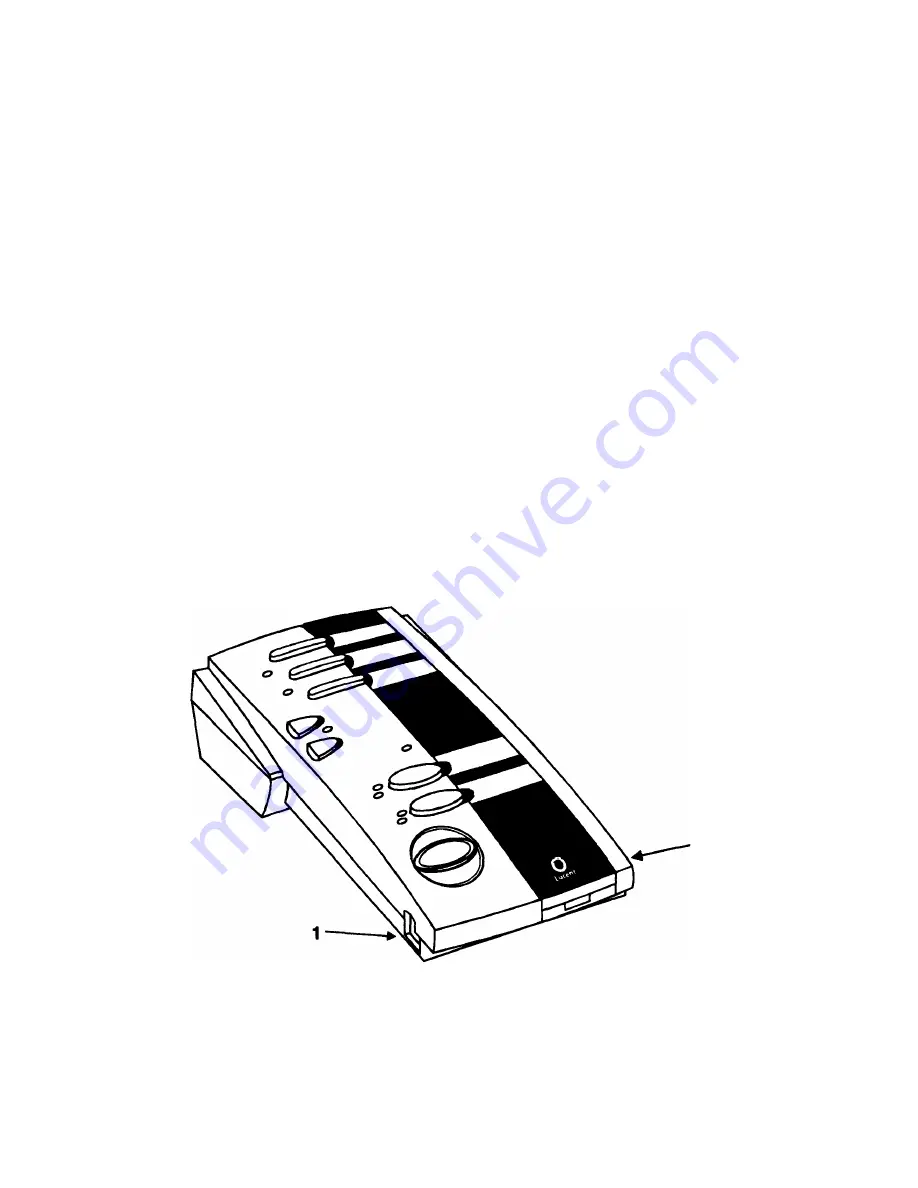
The two headset jacks share the same volume setting. The headset

jacks are not labeled; they are located near the bottom front of the unit

on the right and left sides. See Figure 5 for an example of the headset
jack connections.

1. 4-Pin Connector

2. Quick Disconnect

Figure 5: Connecting the Headset Jacks

To connect the headset, do the following steps:

1.

Insert the 4-pin male connector end of the headset adapter cord

into the headset jack on either the right or left side of the

CALLMASTER  VI.

2. Insert the quick disconnect end of the headset adapter cord into

the headset.

A handset with a custom cable will work if plugged into one of the

headset jacks. The handset is available as a D-Kit.

ABOUT THE CALLMASTER

® 

VI Voice Terminal

The CALLMASTER VI is a miniature, digital-voice terminal. It works in

conjunction with the  DEFINITY

® 

Enterprise Communications Server

(ECS) Release 6.1 and your application software.

The DEFINITY ECS uses the CALLMASTER  VI voice terminal to

download selected DEFINITY ECS configuration data to the
application software. The PC that is running the application software
controls the voice terminal through an EIA/TIA-574 serial port

interface, and full functionality is accessible only from that PC.

Power for the CALLMASTER VI voice terminal, including the headset,

comes from the DEFINITY ECS through the 2-wire DCP line. This

power allows the voice terminal to operate even when local power to

the PC fails.

The following sections explain the features of the CALLMASTER VI,

including the headset jacks, handset, buttons, and announcements

recorder.

Headset Jacks

Headset input jacks are located on both sides of the base of the

CALLMASTER VI voice terminal, as shown in Figure 1. You can plug

headsets into both sides at the same time.

1. Left Headset Jack

2. Right Headset Jack

Figure 1: Headset Jacks

*Registered trademarks of Plantronics, Inc.

†trademarks of Plantronics, Inc.

8

1

Summary of Contents for Callmaster VI

Page 1: ...1 0 Installation and User s Manual Caution Please DO NOT DISCARD this booklet It contains important safety information necessary for anyone responsible for installing or using these terminals 555 015 162 Comcode 107969602 Issue 1 June 1997 ...

Page 2: ...to Avaya Inc Any reference within the text to Lucent Technologies Inc or Lucent should be interpreted as references to Avaya Inc The exception is cross references to books published prior to April 1 2001 which may retain their original Lucent titles Avaya Inc formed as a result of Lucent s planned restructuring designs builds and delivers voice converged voice and data customer relationship manage...

Page 3: ...rference to radio or television reception which can be determined by turning the equipment off and on the user is encouraged to try to correct the interference by one or more of the following measures Reorient or relocate the receiving antennae Increase the separation between the equipment and receiver Plug the equipment into an outlet on a circuit different from that to which the receiver is conn...

Page 4: ...ollowed to reduce the risk of fire electric shock and injury to persons Read and understand all instructions Follow all warnings and instructions marked on the telephone This telephone can be hazardous if immersed in water To avoid the possibility of electric shock do not use it while you are wet If you accidentally drop the telephone into water do not retrieve it until you have first unplugged th...

Page 5: ...hone is subsequently used SERVICE 1 Before cleaning unplug the telephone from the modular wall jack and your personal computer Do not use liquid cleaners or aerosol cleaners Use a damp cloth for cleaning 2 Unplug the telephone from the modular wall jack Be sure to refer servicing to qualified service personnel when these conditions exist If liquid has been spilled into the telephone If the telepho...

Page 6: ...n INSTALLATION WARNING for the CALLMASTER VI MODULAR WALL JACK WIRING Pin Pair Name Description 4 1 BL W 2 Wire Tip 5 1 W BL 2 Wire Ring FAILURE TO FOLLOW THESE INSTRUCTIONS CAN CAUSE DAMAGE TO THE TERMINAL OR CAUSE THE ASSOCIATED DEFINITY ECS CIRCUIT PACK TO REMOVE POWER TO THE TERMINAL IN EITHER CASE THE TERMINAL WILL NOT FUNCTION CORRECTLY For 2 wire operation if you need to plug the voice term...

Page 7: ...ort interface and full functionality is accessible only from that PC Power for the CALLMASTER VI voice terminal including the headset comes from the DEFINITY ECS through the 2 wire DCP line This power allows the voice terminal to operate even when local power to the PC fails The following sections explain the features of the CALLMASTER VI including the headset jacks handset buttons and announcemen...

Page 8: ...Waiting indicator see Figure 5 Six of the buttons represented in Figure 5 can be administered on the DEFINITY ECS These are buttons 1 2 3 7 8 and 9 Voice Announcement Recording The Announcements Recorder feature in the application software and the CALLMASTER VI voice terminal enables recording and playback of personalized announcements You can record up to 6 announcements at a length of 9 6 second...

Page 9: ...f the wire See the following specifications Within 5 500 feet for 22 gauge wire Within 3 500 feet for 24 gauge wire Within 2 200 feet for 26 gauge wire WARNING Failure to follow these instructions can cause damage to the terminal or cause the associated DEFINITY ECS circuit pack to remove power to the terminal In either case the terminal will not function correctly Checklist of Items Before beginn...

Page 10: ...allation Procedures The CALLMASTER VI voice terminal comes with two mounting strips that you can use to mount the unit to the desktop the side of the monitor or the wall in your work area The installation procedures are the same no matter where you mount the unit To mount the strips do the following steps 1 Turn the CALLMASTER VI voice terminal over 2 Remove the backing from one side of the mounti...

Page 11: ...esentative or distributor for assistance Installation Diagram Figure 2 shows the connections between the CALLMASTER VI the DEFINITY ECS and the PC Refer to the figure below when following the installation procedures on the following pages 1 DEFINITY ECS 2 wire DCP Interface 2 PC Serial Port Connector 3 Digital Communications Protocol DCP Interface 4 9 Pin Serial Connector 5 Headset Jacks Figure 2 ...

Page 12: ...sed See Figure 3 for an example of this connection 1 Line labeled 2 Connection to CALLMASTER VI 3 Connection to DEFINITY ECS Figure 3 CALLMASTER VI to DEFINITY ECS Connection To connect the CALLMASTER VI to the DEFINITY ECS do the following steps 1 Insert the modular jack at one end of the line cord into the CALLMASTER VI jack labeled LINE 2 Insert the modular jack at the other end of the line cor...

Page 13: ...Port on the PC Figure 4 CALLMASTER VI to PC Connection To connect the CALLMASTER VI to the PC do the following steps 1 Insert the 9 pin male connector at one end of the EIA TIA cable into the female D subminiature connector located in the back of the CALLMASTER VI labeled EIA Tighten both connector retaining screws 2 Insert the 9 pin female connector at the other end of the EIA TIA cable into an u...

Page 14: ...ons 1 4 Pin Connector 2 Quick Disconnect Figure 5 Connecting the Headset Jacks To connect the headset do the following steps 1 Insert the 4 pin male connector end of the headset adapter cord into the headset jack on either the right or left side of the CALLMASTER VI 2 Insert the quick disconnect end of the headset adapter cord into the headset A handset with a custom cable will work if plugged int...

Page 15: ...Off Mute and Release and the Message indicator The second strip was designed for international applications It has no descriptions but has the CALLMASTER VI name and Lucent logo You would use it to describe buttons in languages other than English You can also use it if you do not want button descriptions or if the blue button is not administered for the Release function The third strip is blank fo...

Page 16: ...n Off 5 Mute 6 Message Waiting 7 Call Appearance 1 8 Call Appearance 2 9 Release Figure 6 The CALLMASTER VI Voice Terminal Log In Button This button is configured on the switch as an abbr dial button programmed to a number associated with the ACD log in As such you can use this button to log in to the DEFINITY ECS This button is administerable Feature Buttons Buttons 2 and 3 on the CALLMASTER VI h...

Page 17: ...ion You can remove your headset without toggling the on hook off hook condition The red status indicator associated with the Mute button serves as an indicator for the Headset On Off function When the CALLMASTER VI is first powered up and after a reset the headset is in the on hook condition When the headset is on hook the status indicator is red meaning the voice path to the headset is turned off...

Page 18: ...cates that the line is in use while the red lamp indicates that there are no calls on the line at the present time These buttons are administrable One suggestion is to configure them as Send All Calls or Call Forwarding buttons for use when the PC goes down Release Button The large blue button has no indicator Pressing the Release button clears the current call This button is administerable but it...

Page 19: ...he following information Write Call Fax Order Lucent Technologies BCS Publications Center P O Box 4100 Crawfordsville IN 47933 Voice 1 800 457 1235 International Voice 1 317 361 5353 Fax 1 800 457 1764 International Fax 1 317 361 5355 When ordering this document be sure to specify the title and the 555 ordering number Lucent Technologies Bell Labs Innovations Copyright 1997 Lucent Technologies All...

Page 20: ...14 ...

Reviews: