background image

INSTALLATION

Avaya 9135 6000 VA UPS Site Preparation, Installation and Operator’s Manual

S

164201769 Rev 1

40

Output Terminal

Input Terminal

GND L2

(N)

L1

GND L2

(N)

L1

Figure 21. Installing the Input and Output Cables

5.

Replace the terminal block cover and tighten the cables.

6.

Secure the terminal block cover with the two screws removed in
Step 1.

7.

Plug the equipment to be protected into the appropriate UPS output
receptacles.

NOTE

If more than one load is connected to the UPS, the total capacity of the loads should

not exceed 30A.

Figure 22. Connecting the Power Cords

Summary of Contents for 9135 6000 VA

Page 1: ...Avaya 9135 6000 VA Uninterruptible Power Systems Site Preparation Installation and Operator s Manual www powerware com avaya ...

Page 2: ......

Page 3: ...Avaya 9135 6000 VA Uninterruptible Power Systems Site Preparation Installation and Operator s Manual www powerware com avaya ...

Page 4: ...r products with a CE mark For copies of the EC Declaration of Conformity contact Eaton Power Quality Oy Koskelontie 13 FIN 02920 Espoo Finland Phone 358 9 452 661 Fax 358 9 452 665 68 Avaya and the Avaya logo are trademarks of Avaya Inc and may be registered in certain jurisdictions Eaton and LanSafe are registered trademarks and ConnectUPS is a trademark of Eaton Corporation or its subsidiaries a...

Page 5: ...installed and used in accordance with the instruction manual may cause harmful interference to radio communications Operation of this equipment in a residential area is likely to cause harmful interference in which case the user will be required to correct the interference at his own expense EN 62040 2 Some configurations are classified under EN 62040 2 as Category C2 UPS For these configurations ...

Page 6: ...tion such as important operating and maintenance instructions This symbol indicates that you should not discard the UPS or the UPS batteries in the trash This product contains sealed lead acid batteries and must be disposed of properly For more information contact your local recycling reuse or hazardous waste center This symbol indicates that you should not discard waste electrical or electronic e...

Page 7: ...Tower Setup 30 Installing the UPS 35 RPO Installation 37 UPS Electrical Connections 38 Recommended Upstream Protection 38 Required Cable Cross Sections 38 Connecting the Power Cables 39 UPS Rear Panel 41 4 Operation 43 Control Panel Functions 43 Turning the UPS On 44 Starting the UPS on Battery 44 Turning the UPS Off 45 Operating Modes 45 Normal Mode 46 Eco Mode 46 Battery Mode 46 Bypass Mode 47 D...

Page 8: ...ipate Maintenance 53 Reset or Disable LCM 54 5 Additional UPS Features 55 USB Port 55 Relay Port 56 6 Maintenance 59 Hot Swapping the Power Module 59 Hot Swapping the Battery Tray 60 7 Specifications 61 8 Troubleshooting 63 Troubleshooting LED 63 Troubleshooting Not Requiring Avaya Service 64 Troubleshooting Requiring Avaya Service 65 Obtaining Service 66 Parts List 66 ...

Page 9: ...gh voltage spikes frequency variations switching transients and harmonic distortion Power outages can occur when you least expect it and power quality can be erratic These power problems have the potential to corrupt critical data destroy unsaved work sessions and damage hardware causing hours of lost productivity and expensive repairs With the Avaya 9135 you can safely eliminate the effects of po...

Page 10: ...n or as a standalone cabinet S Hours of extended runtime with up to six EBMs per UPS S Start on battery capability for powering up the UPS even if utility power is not available S Hot swappable power module and battery tray that simplify maintenance by allowing you to replace them safely without powering down the critical load S Shutdown control through the remote power off RPO port S Two standard...

Page 11: ...arry live voltage even when the UPS is not connected to an AC supply S For 208 240V models the output receptacles may remain electrically live If the input power source in your application is wired line to neutral as in most European applications the voltage to the output receptacles is 0V With line to line input wiring the voltage to the output receptacles is 110 120V measured from line to ground...

Page 12: ...FARE Denne UPS indeholder LIVSFARLIG HØJSPÆNDING Alle reparationer og vedligeholdelse bør kun udføres af en AUTORISERET SERVICETEKNIKER Ingen af UPS ens indvendige dele kan repareres af brugeren ADVARSEL S Denne UPS indeholder sin egen energikilde batterier Udgangsstikket på UPS en kan endog være strømførende når UPS en ikke er koblet til en vekselstrømsforsyning S På 208 240V modeller kan udgangs...

Page 13: ...e instructies voordat u de apparatuur in bedrijf neemt en bewaar deze handleiding als naslagwerk GEVAAR Deze UPS bevat LEVENSGEVAARLIJKE ELEKTRISCHE SPANNING Alle reparaties en onderhoud dienen UITSLUITEND DOOR ERKEND SERVICEPERSONEEL te worden uitgevoerd Er bevinden zich GEEN ONDERDELEN in de UPS die DOOR DE GEBRUIKER kunnen worden GEREPAREERD WAARSCHUWING S Deze UPS bevat een eigen energiebron a...

Page 14: ...atterijen leveren gevaar op voor elektrische schokken en kunnen brandwonden veroorzaken door een grote kortsluitstroom Neem de juiste voorzorgsmaatregelen in acht Het onderhoud moet worden uitgevoerd door bevoegde onderhoudsmonteurs die verstand hebben van accu s en op de hoogte zijn van de vereiste voorzorgsmaatregelen Houd onbevoegden uit de buurt van de accu s S De batterijen moeten op de juist...

Page 15: ...jännite on 0 V Linjasta linjaan tulojohdotuksessa lähtövastakkeiden jännite on 110 120 V mitataan linjasta maahan tai linjasta neutraaliin UPS virtalähteen johdotuksesta riippuen S Älä poista tai irrota sisääntulojohtoa kun UPS on kytkettynä Tämä poistaa turvamaadoituksen UPS laitteesta ja siihen liitetystä laitteistosta S Vähentääksesi tulipalon ja sähköiskun vaaraa asenna tämä UPS sisätiloihin j...

Page 16: ... de l onduleur soit sous tension même lorsque l onduleur n est pas connectée à une alimentation CA S En ce qui concerne les modèles 230 V il est possible que les prises de sortie restent sous tension Si la source d alimentation de votre application est câblée phase et neutre comme dans la majorité des applications européennes la tension vers les prises de sortie est de 0 V Avec un câblage d entrée...

Page 17: ...hrend der Installation und Wartung des USV Unterbrechungsfreies Stromversorgungssystem und der Batterien befolgen müssen Bitte lesen Sie alle Anweisungen des Handbuches bevor sie mit dem Gerät arbeiten Bewaren Sie das Handbuch zum Nachlesen auf WARNUNG Die USV führt lebensgefährliche Spannungen Alle Reparatur und Wartungsarbeiten sollten nur von Kundendienstfachleuten durchgeführt werden Die USV e...

Page 18: ...cht in der Nähe von Wasser oder in extrem hoher Luftfeuchtigkeit max 95 betreiben VORSICHT S Batterien können das Risiko eines elektrischen Schlags bergen oder durch hohen Kurzschlussstrom in Brand geraten Die richtigen Vorsichtsmaßnahmen beachten Die Wartung muss von qualifiziertem Wartungspersonal durchgeführt werden das im Umgang mit Batterien geübt ist und über gute Kenntnisse der erforderlich...

Page 19: ...legato all alimentazione elettrica CA S Nei modelli da 230 V è possibile che le prese d uscita rimangano sotto tensione Se la fonte di alimentazione in entrata dell installazione è costituita da un collegamento linea neutro come accade nella maggior parte delle installazioni europee la tensione delle prese d uscita è pari a 0 V Con un cablaggio in entrata del tipo linea linea la tensione sulle pre...

Page 20: ...istenza deve essere eseguita da personale qualificato esperto di batterie e delle necessarie precauzioni Tenere il personale non autorizzato lontano dalle batterie S Le batterie devono essere smaltite in modo corretto Per i requisiti di smaltimento fare riferimento alle disposizioni locali S Non gettare mai le batterie nel fuoco poichè potrebbero esplodere se esposte alle fiamme S Sostituire le ba...

Page 21: ...ngsstikkene være 110 120 V målt fra fase til jord eller fase til nøytral avhenging av UPS ledningsføringen S For å redusere fare for brann eller elektriske støt bør denne UPS en installeres i et innendørs miljø med kontrollert temperatur og luftfuktighet som er fritt for ledende forurensende stoffer Romtemperaturen må ikke overskride 40 C Den må ikke brukes i nærheten av vann eller ved meget høy l...

Page 22: ...sua aplicação for do tipo fase neutro como ocorre na maioria das aplicações na Europa a tensão das tomadas de saída é de 0 V Com a alimentação fase fase a tensão das tomadas de saída é de 110 120 V medida como fase terra ou fase neutro dependendo da instalação elétrica do no break S Não remova ou desconecte o cabo de entrada quando a UPS estiver ligada Isto removerá o aterramento de segurança da U...

Page 23: ...данном ИБП установлены собственные источники энергии батареи В ИБП может иметься напряжение даже в том случае если он не подключен к сети переменного тока S На выходных розетках моделей с напряжением 230 В может быть напряжение Если устройство рассчитано на тип подключения фаза нейтраль как большинство устройств изготавливаемых в Европе напряжение на выходных розетках равно 0 В При типе подключени...

Page 24: ... las baterías Por favor lea todas las instrucciones antes de poner en funcionamiento el equipo y guarde este manual para referencia en el futuro PELIGRO Este SIE contiene VOLTAJES MORTALES Todas las reparaciones y el servicio técnico deben ser efectuados SOLAMENTE POR PERSONAL DE SERVICIO TÉCNICO AUTORIZADO No hay NINGUNA PARTE QUE EL USUARIO PUEDA REPARAR dentro del SIE ADVERTENCIA S Este SIE con...

Page 25: ...aterías con el mismo número y tipo de baterías como se instalaron originalmente en el SAI Säkerhetsföreskrifter VIKTIGA SÄKERHETSFÖRESKRIFTER SPARA DESSA FÖRESKRIFTER Den här anvisningen innehåller viktiga instruktioner som du ska följa under installation och underhåll av UPS enheten och batterierna Läs alla instruktioner innan du använder utrustningen och spara den här anvisningen för framtida re...

Page 26: ...nde temperatur får ej överstiga 40 C Använd inte utrustningen nära vatten eller vid hög luftfuktighet max 95 VIKTIGT S Batterierna kan innebära en risk för elektrisk stöt eller brännskada från kortsluten starkström Iakttag lämpliga försiktighetsåtgärder Service ska utföras av utbildad servicepersonal med kunskap om batterierna och nödvändiga försiktighetsåtgärder Håll ej behörig personal borta frå...

Page 27: ... keep the shipping cartons and packing materials for the carrier or place of purchase and file a claim for shipping damage If you discover damage after acceptance file a claim for concealed damage To file a claim for shipping damage or concealed damage 1 File with the carrier within 15 days of receipt of the equipment 2 Send a copy of the damage claim within 15 days to your Avaya service represent...

Page 28: ... destroyed according to waste management standards Recycling icons are displayed for easy selection Verify that the following additional items are included with the UPS Table 1 UPS Accessory Kit Item Description UPS user s guide or CD Screwdriver RS 232 serial cable Rackmounting kit for 19 inch 48 cm bays Two sets of pedestals with screws for tower position ...

Page 29: ... If you ordered an optional EBM verify that the following items are included with the EBM Table 2 EBM Accessory Items Item Description EBM user s guide EBM cable EBM communication cable Rackmounting kit for 19 inch 48 cm bays Pedestal extenders for tower position Joining bracket and screws for tower position ...

Page 30: ... battery operation 1 Verify that the UPS is off and unplugged 2 Remove the two screws from the battery switch see Figure 2 Two Screws Battery Switch Figure 2 Removing the Battery Switch Screws 3 Slide the battery connector so that you can read Connected see Figure 3 4 Reinstall the two screws removed in Step 2 Figure 3 Connecting the Internal Battery Connector ...

Page 31: ...rack continue to the following section Rackmount Setup otherwise continue to Tower Setup on page 30 Rackmount Setup The rail kit can be mounted in 19 inch panel 48 cm racks from 24 to 30 inches 61 to 76 cm deep and includes S Left and right sliding rail assemblies S 20 M4 6 mm Phillips flat head screws S 4 M4 10 mm Phillips round head screws S 4 M6 12 mm Phillips round head screws S 8 M6 12 mm Phi...

Page 32: ...e heavy see page 61 1 Avaya strongly recommends to remove the battery tray from the UPS before lifting 2 A minimum of two people are required to lift the cabinets into the rack NOTE The rails and the necessary mounting hardware are supplied by Avaya To install the rail kit 1 Adjust the UPS control panel orientation by slightly pulling out the control panel and rotating it 90 counterclockwise see F...

Page 33: ... tray see Figure 5 S Remove the UPS front cover six screws NOTE A ribbon cable connects the control panel to the UPS Do not pull on the cable or disconnect it S Place the front panel above the UPS S Remove the two battery retaining brackets four screws S Slightly pull the battery tray then lift it to extract it Figure 5 Removing the Battery Tray ...

Page 34: ...face with the front of the cabinet facing you NOTE You can adjust the position of the mounting brackets 4 Align the mounting brackets with the screw holes on the side of the cabinet and secure with the supplied M4 6 mm flat head screws 5 If installing additional cabinets repeat Steps 3 and 4 for each cabinet Figure 6 Installing the Mounting Brackets ...

Page 35: ...ust the rail size for the depth of your rack see Figure 7 7 Select the proper holes in the rail for positioning the UPS in the desired location in the rack 8 Using two M6 12 mm flat head screws attach the rail to the rear of the rack 9 Secure the rail to the front of the rack with two M6 12 mm screws 10 Repeat Steps 8 and 9 for the other rail Figure 7 Installing the Rails ...

Page 36: ...cluded with the rail kit if you need to move the rack enclosure with the UPS already rack mounted inside see Figure 8 Figure 8 Installing the Rear Hold Down Brackets 12 Slide the UPS and any optional EBMs into the rack 13 Secure the front of the cabinet to the rack using two M6 12 mm round head screws on each side see Figure 9 Figure 9 Installing the Cabinets ...

Page 37: ...r hold down brackets secure the brackets to the rear rails using two screws for each bracket see Figure 10 Figure 10 Securing the Rear Hold Down Brackets 15 If you removed the UPS battery tray in Step 2 replace the battery tray and secure with the battery retaining brackets Replace the UPS front cover 16 Continue to Installing the UPS on page 35 ...

Page 38: ...are installing 1 Assemble the UPS pedestals see Figure 11 Figure 11 Assembling the UPS Pedestals 2 For one cabinet the pedestals must be installed Continue to Step 3 For two or more cabinets the pedestal extenders and the joining brackets must be installed Proceed to Step 6 NOTE Always keep 150 mm free space behind the UPS rear panel The distance between the tower stands should be 450 mm 3 Careful...

Page 39: ...vaya 9135 6000 VA UPS Site Preparation Installation and Operator s Manual S 164201769 Rev 1 31 150 mm 6 450 mm 17 7 UPS Indicators Figure 12 Tower Position with One Cabinet 5 Continue to Installing the UPS on page 35 ...

Page 40: ... additional cabinet For two cabinets insert the extender into position 3 on the pedestal see Figure 13 For three cabinets or more insert the extender into position 4 on the pedestal see Figure 14 4 3 2 1 4 3 2 1 Figure 13 Extending the Pedestals for Two Cabinets 4 3 2 1 4 3 2 1 4 3 2 1 Figure 14 Extending the Pedestals for Three or More Cabinets ...

Page 41: ...Manual S 164201769 Rev 1 33 7 Carefully position the cabinet upright with the UPS indicators at the top and place in the pedestals see Figure 15 8 Adjust the pedestals to the size of the UPS and secure the pedestals with the captive screws Figure 15 Tower Position with Two Cabinets ...

Page 42: ...th the adjacent cabinet screw holes and secure with the supplied screws see Figure 16 NOTE Joining brackets are required for installations with two or more cabinets Joining Bracket Figure 16 Installing the Joining Brackets 10 If installing additional EBMs repeat Step 6 for each cabinet 11 Continue to the following section Installing the UPS ...

Page 43: ... model To install the UPS and optional EBMs 1 If installing an optional EBM continue to Step 2 otherwise continue to Step 6 2 Verify that the EBM battery circuit breaker is OFF 3 Plug the EBM cable into the battery connector see Figure 17 Up to six EBMs may be connected to the UPS 4 For one to four EBMs Plug the EBM communication cable into the RJ 11 port NOTE If there are five or more EBMs do not...

Page 44: ...ommunication Cable EBM Cable EBM Battery Connectors Battery Circuit Breaker Figure 17 UPS Installation with Three EBMs 6 If you are installing a remote power off RPO switch see the following section RPO Installation to install the switch before powering on the UPS 7 Continue to UPS Electrical Connections on page 38 ...

Page 45: ...his RPO switch to a device that trips all breaker s located upstream 1 and downstream 2 the Avaya 9135 UPS This can be achieved by means of a shunt trip 1 If not the output devices could be powered again through static switch when the two position switch is released 2 If not the output devices will remain powered several seconds after the RPO activation NOTE The internal batteries will remain conn...

Page 46: ... for the output AC circuit s are to be provided by others Recommended Upstream Protection The indicated protection ensures discrimination for each output circuit downstream of the UPS If these recommendations are not followed protection discrimination is not achieved and may result in a potential power interruption to the connected devices UPS Power Rating Upstream Circuit Breaker 6000 VA D curve ...

Page 47: ...O S Use included insulated ferrules with stranded wires 1 Remove the terminal block cover two screws with the supplied screwdriver see Figure 20 B ATT N O 2 00 25 0V 2 4 A R P O R S 2 3 2 C A U T IO N D O N O T D IS C O N N E C T B A T T E R Y C A B LE U N D E R L O A D B A TT E RY C O N N E C T O R 1 8 0 VD d c Input Cable Output Cable Opening Figure 20 Removing the Terminal Block 2 Connect the t...

Page 48: ...ng the Input and Output Cables 5 Replace the terminal block cover and tighten the cables 6 Secure the terminal block cover with the two screws removed in Step 1 7 Plug the equipment to be protected into the appropriate UPS output receptacles NOTE If more than one load is connected to the UPS the total capacity of the loads should not exceed 30A Figure 22 Connecting the Power Cords ...

Page 49: ...ws the 6000 VA Avaya 9135 UPS rear panel BATT NO 200 250V 24A RPO RS 232 CAUTION DO NOT DISCONNECT BATTERY CABLE UNDER LOAD BATTERY CONNECTOR 180VDdc 4 L6 30 Receptacles Network Management Card Relay Port RPO Port EBM RJ 11 Connector Output Terminal Block Input Cord with L6 30P EBM Battery Connector USB Port RS 232 Port Figure 23 6000 VA ...

Page 50: ...INSTALLATION Avaya 9135 6000 VA UPS Site Preparation Installation and Operator s Manual S 164201769 Rev 1 42 ...

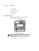
Page 51: ...nctions Control Panel Functions The UPS has a four button graphical LCD with backlight It provides useful information about the UPS itself load status events measurements and settings see Figure 24 esc Power Indicator Battery Indicator Bypass Indicator Alarm Indicator On Off Button Escape Up Down Enter Figure 24 UPS Control Panel NOTE The On Off button controls only the UPS output The On Off butto...

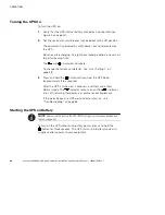
Page 52: ... the factory set defaults see User Settings on page 48 3 Press and hold the button until you hear the UPS beep approximately three seconds After the UPS is turned on it conducts a self test and enters Normal mode The indicator remains on and the indicator turns off indicating that power is available to your equipment If the alarm beeps or a UPS alarm indicator stays on see Troubleshooting on page ...

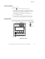
Page 53: ...ment will not be powered If the utility power is out of tolerance the UPS will generate a 10 ms output calibrated break 2 For a full shutdown of UPS and connected load the upstream circuit breaker not included should be set to the OFF position Operating Modes The Avaya 9135 front panel indicates the UPS status through the UPS indicators Figure 25 shows the UPS front panel indicators and controls e...

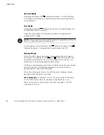
Page 54: ...nce the indicator flashes and the indicator illuminates The equipment is protected by the UPS Battery Mode When the UPS is operating during a power outage the alarm beeps once every five seconds and the and indicators illuminate The equipment is protected by the UPS and supplied by the battery The display shows the remaining battery backup time If battery capacity becomes low while in Battery mode...

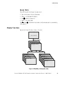
Page 55: ...is a malfunction The and indicators illuminate and the equipment is powered by utility power Display Functions Figure 26 shows the basic menu structure Status and Alarms Measurements Maintenance UPS Setup UPS Input Measurements Status and Alarms UPS Output Measurements Battery Measurements Local Settings Output Settings ON OFF Settings Battery Settings Model Alarm History Manual Batt Test LED Buzz...

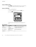
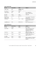
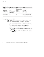
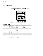
Page 56: ...e UPS Setup menu 1 Scroll to the UPS Setup menu by pressing the button 2 Press the button to get access esc Figure 27 Access to UPS Setup The following tables display the options that can be changed by the user Table 3 Local Settings Function Factory Setting Options Language English French German Italian Portuguese Spanish Date Time Format International DD MM YYYY HH MM US MM DD YYYY HH MM AM PM D...

Page 57: ...s 20 ms 200 ms Break time calibration during load transfer on utility power out of tolerance Overload Prealarm 105 40 50 70 Alarm if threshold is overrun Table 5 ON OFF Settings Function Factory Setting Options Comments Cold Start Disable Enable Start on battery Forced Reboot Enable Enables automatic restart of the system even if utility power is restored before the end of the shutdown sequence Au...

Page 58: ...inst deep discharge If disabled the Avaya warranty will be void Configuring the UPS for EBMs NOTE The UPS automatically configures up to four EBMs with the EBM communication cable installed Use the following steps for installations with five or more EBMs To ensure maximum battery runtime for installations with five or more EBMs configure the UPS for the correct number of EBMs 1 Scroll to the UPS S...

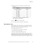
Page 59: ...ntil the status screen appears Running Battery Tests Automatic battery tests run every week unless modified through the UPS User Settings menu see Table 6 You can change the automatic battery test to run every day every month or not at all For an automatic battery test to run S The Auto Battery Test setting must be enabled S The UPS must be in Normal mode S The bypass voltage must be greater than ...

Page 60: ...ys the maintenance options Table 7 Maintenance Settings Function Sub Function Option Display Comments Model Power Module SN xxxxxxxxx SOFT xxx Serial number Soft version Frame Alarm History Read Description Date Hour Alarm xxx 10 alarms can be stored automatically Erase No Yes Manual Batt Test Manual Battery Test No Yes Led Buzzer Test Led Buzzer Test No Yes Life Cycle Monitoring LCM Enable Disabl...

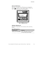
Page 61: ...channels at every important stage of the UPS s life Press the button to display LCM warning details esc Figure 29 LCM Warning Screen Anticipate Maintenance Automatic warnings appear when maintenance actions need to be planned Table 8 LCM Warning Details LCM Warning Details Signification BATTERY CHECK RECOMMENDED Battery is approaching its reliability end of life Risk to reduce dramatically backup ...

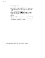
Page 62: ...e in the Status and Alarm menu to temporarily cancel the alarm status The alert will be repeated twice every 30 days S For permanent reset press the button for at least three seconds while in the LCM warning menu to permanently cancel the LCM event At any time S To disable all LCM messages select disable all while in the LCM menu Be careful if you disable all LCM messages you will not be aware of ...

Page 63: ...protection of IT systems USB Port The UPS can communicate with a USB compliant computer using LanSafe Power Management Software or other HID compliant power management software compatible with Microsoft Windows 2000 and XP operating systems that support HID devices NOTE The latest versions of the LanSafe Power Management Software and the USB firmware are available at www powerware com To establish...

Page 64: ...ATTERY CONNECTOR 180VDdc Figure 30 The USB Port 2 Install the LanSafe Power Management Software and USB drivers according to the instructions provided at www powerware com Relay Port When the status is active the contact between the common Pin 5 and the relevant information pin is closed Output relays specifications S Voltage 48 Vdc maximum S Current 2A maximum S Power 62 5 VA 30W Example for 48 V...

Page 65: ...pin functions NOTE Normally open NO Normally closed NC Common NC NO NO NO NO 7 8 6 9 3 5 4 2 1 Figure 31 Communication Port Table 9 Communication Port Pin Assignment Pin Number Function 1 2 Not used 3 Remote power off RPO signal 5 27 Vdc 10 mA max 4 Operation on mains not on battery 5 User common 6 Operation on automatic bypass 7 Low Battery 8 Load protected 9 Operation on battery ...

Page 66: ...ADDITIONAL UPS FEATURES Avaya 9135 6000 VA UPS Site Preparation Installation and Operator s Manual S 164201769 Rev 1 58 ...

Page 67: ... This operation can be performed without interrupting the equipment 1 Remove the UPS front cover six screws See Figure 32 NOTE A ribbon cable connects the control panel to the UPS Do not pull on the cable or disconnect it 2 Place the front panel above the UPS 3 Remove the two power module brackets four screws 4 Slightly pull the power module then lift it to extract it Figure 32 Removing the Power ...

Page 68: ...Use tools with an insulated handle S When replacing batteries replace with the same number of the BB HR5 5 12 batteries This operation can be performed without interrupting the equipment 1 Remove the UPS front cover six screws See Figure 33 NOTE A ribbon cable connects the control panel to the UPS Do not pull on the cable or disconnect it 2 Place the front panel above the UPS 3 Remove the two batt...

Page 69: ...justed using the UPS front panel see page 48 2 Up to 40 Hz in low sensitivity mode programmable using the UPS front panel see page 48 3 Adjustable to 200V 10 derating of output power 208 220 230 240 250V Table 11 Dimensions and Weights Model Dimensions WxHxD Weight 6000 VA UPS 444 5 130 6 741 mm 17 5 5 1 29 2 57 kg 125 7 lb UPS Power Module 198 127 603 mm 7 8 5 23 7 12 kg 26 5 lb UPS Internal Batt...

Page 70: ...Category B IEC 61000 4 5 Safety Conformance UL 1778 CSA C22 2 No 107 1 NOM 019 SCFI Agency Markings cUL NOM EMC Class A FCC Part 15 Table 14 Battery UPS Configuration 15 12V 5 5 Ah internal batteries EBM Configuration 2 strings of 15 12V 5 5 Ah internal batteries Type Sealed maintenance free lead acid Recharge Time to 90 Internal batteries 6 hours 1 EBM 5 hours 2 EBMs 8 hours 3 EBMs 13 hours 4 EBM...

Page 71: ...plains S UPS alarms and conditions S Service and support Troubleshooting LED Press the esc button to stop the audible alarm NOTE In case of MULTIPLE FAULT press the button and the button to get access to further details NOTE In case of LCM WARNING see Life Cycle Monitoring on page 53 esc Escape Up Down Enter Figure 34 Troubleshooting LED ...

Page 72: ...CONNECTION Utility input is not connected to the correct terminals Check AC wiring NO POWER MODULE The power module is not inserted Check power module connections see page 59 NO BATTERY MODULE The battery tray is incorrectly connected Check battery connections see page 60 INV THERM OVERLOAD The UPS shuts down automatically because of a major overload Check the power drawn by the connected devices ...

Page 73: ...LED Display Signification Correction POWER MODULE FAULT Internal power module fault detected Use Enter button to display details In Parallel see the note below to start the other UPS alone Call the Help Desk Replace the power module see page 59 BATT MODULE FAULT Battery fault detected during the battery test Use Enter button to display details Call the Help Desk Replace the battery tray see page 6...

Page 74: ...UPS call your Avaya service representative or the appropriate telephone number on the service label of your UPS Please have the following information ready when you call S Material code S Serial number S Version number if available S Date of failure or problem S Symptoms of failure or problem S Customer return address and contact information Parts List SAP Code Description 700465446 6000 VA 120V U...

Page 75: ......

Page 76: ...340 08710 AA 1642017691 164201769 1 ...

Reviews: