background image

ASSEMBLY INSTRUCTIONS

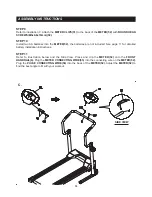
STEP 6

Refer to the illustration below. Attach the 

RIGHT HANDRAIL(5R),

 the one with 

EXTENSION WIRE(54), 

to the 

RIGHT UPRIGHT(4)

 with 

BUTTON HEAD BOLTS(M8x1.25x40)(34)

 and 

ARC WASHERS(M8)(60). 

Attach the 

LEFT HANDRAIL(5L)

 to the 

LEFT UPRIGHT(3)

 with 

BUTTON HEAD BOLTS(M8x1.25x40)

(34)

 and 

ARC WASHERS(M8)(60). DO NOT TIGHTEN THE BUTTON HEAD BOLTS(M8x1.25x40)(34). 

STEP 7

Plug the 

EXTENSION WIRE(54)

  into the 

METER CONNECTING WIRE(55). 

Connect the 

PULSE 

SENSOR WIRES(62)

  to the 

PULSE CONNECTING WIRES(56). 

Push the wires back inside of the 

LEFT

 and 

RIGHT HANDRAILS(5L, 5R). 

Insert the 

FRONT HANDRAIL(6)

 onto the 

LEFT

 and 

RIGHT 

HANDRAILS(5L, 5R)

 and secure with the 

ROUND HEAD BOLTS(M6x1x15mm)(39).

STEP 8

Securely tighten the 

BUTTON HEAD BOLTS(M8x1.25x40)(34)

 from 

STEP 6.

 Connect the 

EXTENSION 

WIRE(54)

 which is attached on the 

RIGHT HANDRAIL(5R)

 to the 

SENSOR CONNECTING WIRE(53). 

Press the 

HANDRAIL CAPS(48)

 onto the 

LEFT

 and 

RIGHT HANDRAILS(5L, 5R)

 to cover the top ends 

of the 

LEFT

 and 

RIGHT UPRIGHTS(3, 4).

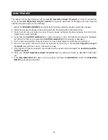
9

Summary of Contents for A450-261

Page 1: ...Products Inc 2014 05 Exercise can present a health risk Consult a physician before beginning any exercise program with this equipment If you feel faint or dizzy immediately discontinue use of this equipment Serious bodily injury can occur if this equipment is not assembled and used correctly Serious bodily injury can also occur if all instructions are not followed Keep others and pets away from eq...

Page 2: ...ore using always check the Main Frame 1 is locked securely with the Locking Knob 44 12 Consult a physician prior to commencing an exercise program and follow his her recommendations in developing your fitness program If at any time during exercise you feel faint dizzy or experience pain stop and consult your physician 13 Always choose the workout which best fits your physical strength and flexibil...

Page 3: ...our Customer Service Department toll free number 1 800 375 7520 Monday Thursday 7 30 A M 5 00 P M Central Time Friday 8 00 A M 3 00 P M Central Time TELEPHONE CUSTOMER SERVICE Tel 1 800 375 7520 FAX CUSTOMER SERVICE Fax 417 889 8064 MAIL STAMINA PRODUCTS INC ATTN Customer Service P O Box 1071 Springfield MO 65801 1071 ONLINE CUSTOMER SERVICE customerservice staminaproducts com www staminaproducts ...

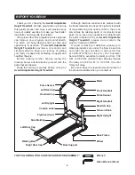
Page 4: ...ieving a happier and healthier lifestyle Before reading further please review the drawing below and familiarize yourself with the parts that are labeled Read this manual carefully before using the Avari Adjustable Height Treadmill Although Stamina constructs its products with the finest materials and uses the highest standards of manufacturing and quality control there can sometimes be missing par...

Page 5: ...tice labels on the Avari Adjustable Height Treadmill Please take a moment to familiarize yourself with all of the warning caution and notice labels EQUIPMENT WARNING CAUTION NOTICE LABELS CAUTION LABEL 63 C1 Labels are larger than actual size 5 MAINTENANCE DECAL 37 C2 ...

Page 6: ...er Use the small scale to check the length of the bolts and screws NOTICE The length of all bolts and screws except those with flat heads is measured from below the head to the end of the bolt or screw Flat head bolts and screws are measured from the top of the head to the end of the bolt or screw After unpacking the unit open the hardware bag and make sure that you have all the following items So...

Page 7: ...u from 7 30 A M to 5 00 P M Central Time Monday through Thursday and 8 00 A M to 3 00 P M Central Time on Friday STEP 1 Remove the Avari Adjustable Height Treadmill from its packing carton the main assembly of the product is shown in view 1 Turn the main assembly up side down as shown in view 2 Attach the REAR SUPPORTS 23 to the MAIN FRAME 1 with BUTTON HEAD BOLTS M8x1 25x45mm 22 and NYLOCK NUTS M...

Page 8: ...the LEFT and RIGHT UPRIGHTS 3 4 to the BASE FRAME 2 with CARRIAGE BOLTS M8x1 25x45 42 WASHERS M8 61 and NYLOCK NUTS M8x1 25 19 STEP 4 Refer to the detail view Lock the MAIN FRAME 1 in the unfolded position by inserting the LOCKING KNOB 44 through the hole in the LEFT UPRIGHT 3 and screwing it into the MAIN FRAME 1 STEP 5 Install the TENSION KNOB 45 into the opening in the RIGHT UPRIGHT 4 and secur...

Page 9: ...RE 54 into the METER CONNECTING WIRE 55 Connect the PULSE SENSOR WIRES 62 to the PULSE CONNECTING WIRES 56 Push the wires back inside of the LEFT and RIGHT HANDRAILS 5L 5R Insert the FRONT HANDRAIL 6 onto the LEFT and RIGHT HANDRAILS 5L 5R and secure with the ROUND HEAD BOLTS M6x1x15mm 39 STEP 8 Securely tighten the BUTTON HEAD BOLTS M8x1 25x40 34 from STEP 6 Connect the EXTENSION WIRE 54 which is...

Page 10: ...es are not included See page 11 for detailed battery installation instructions STEP 11 Refer to illustration below and the Side View Press and clip the METER 52 onto the FRONT HANDRAIL 6 Plug the METER CONNECTING WIRE 55 into the connecting wire on the METER 52 Plug the PULSE CONNECTING WIRE 56 into the back of the METER 52 Adjust the METER 52 to find the best angle to fit with your workout 10 C S...

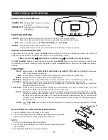
Page 11: ...gh the functions as follows and allow you to set the function values TIME 0 00 to 99 00 DISTANCE 0 0 to 999 0 mile CALORIES 0 0 to 999 0 Kcal Use SET RESET buttons to enter desired values and press MODE button to confirm and move to next function for presetting To pass the setting of some functions just press the MODE button Start to run the Meter functions by walking Automatically scans TIME SPEE...

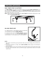
Page 12: ...LOCKWISE and the right screw 1 4 turn COUNTERCLOCKWISE Walk on the treadmill to check alignment Repeat if needed BELT DRIFTING RIGHT Adjust by turning the left screw 1 4 turn COUNTERCLOCKWISE and the right screw 1 4 turn CLOCKWISE Walk on the treadmill to check alignment Repeat if needed NOTE When you believe the WALKING BELT 11 is centered use the treadmill for three 3 minutes to verify the WALKI...

Page 13: ...uctions to adjust belt tension 3 The belt resistance can be reduced by adding silicone lubricant between the belt and the board Wipe the board under the belt with a clean dry cloth then spray or spread silicone lubricant on the board under the belt MAIN FRAME HEIGHT ADJUSTMENT The MAIN FRAME 1 can incline to three different heights by moving the REAR SUPPORTS 23 up or down Insert the PULL PINS 20 ...

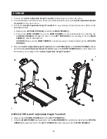
Page 14: ...nserting the LOCKING KNOB 33 through the hole in the LEFT UPRIGHT 3 and screwing it into the MAIN FRAME 1 4 Move the Avari Adjustable Height Treadmill with the WHEELS 40 on the BASE FRAME 2 Stand behind the Avari Adjustable Height Treadmill grasp the FRONT HANDRAIL 6 on both sides and tilt it toward you to easily roll the Avari Adjustable Height Treadmill a Remove the LOCKING KNOB 44 to unlock the...

Page 15: ...ts 4 Verify that the CAUTION LABEL 63 is in place and easy to read Call Stamina Products immediately at 1 800 375 7520 for a replacement CAUTION LABEL 63 if it is missing or damaged 5 It is the sole responsibility of the user owner to ensure that regular maintenance is performed 6 Worn or damaged components shall be replaced immediately or the Avari Adjustable Height Treadmill removed from service...

Page 16: ... of your maximum heart rate zone Start at the lower intensity and build up to higher intensity as you become more aerobically fit If you feel dizzy or lightheaded you should slow down or stop exercising To determine if you are working out at the correct intensity use a heart rate monitor or use the table below For effective aerobic exercise your heart rate should be maintained at a level between 6...

Page 17: ...r cool down should include the stretches listed above and should be completed after each strength training session Lower Body Stretch Place feet shoulder width apart and lean forward Keep this position for 30 seconds using the body as a natural weight to stretch the backs of the legs DO NOT BOUNCE When the pull on the back of the legs lessens gradually try a lower position Floor Stretch While sitt...

Page 18: ...PRODUCT PARTS DRAWING 18 FRONT BACK ...

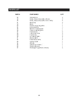
Page 19: ...Button Head M8 x 1 25 x 45mm 2 23 Rear Support 2 24 Grommet Plug 3 25 Plastic Washer ø10 2 x ø25 x 4mm 2 26 Square Plug 20mm x 20mm 4 27 Screw Round Head M4 x 15mm 2 28 Nut M6 x 1 1 29 Bolt Round Head M6 x 1 x 20mm 1 30 Spring 1 31 Plastic Washer ø8 2 x ø16 x 3mm 1 32 Bolt Hex Head M8 x 1 25 x 75mm 1 33 Screw Flat Head M4 x 25mm 8 34 Bolt Button Head M8 x 1 25 x 40mm 4 35 Sensor Wire 1 36 Screw Ro...

Page 20: ...lip 2 52 Meter 1 53 Sensor Connecting Wire 1 54 Extension Wire 1 55 Meter Connecting Wire 1 56 Pulse Connecting Wire 1 57 Pulse Sensor 2 58 Long Foam Tube 2 59 Foam Tube 2 60 Arc Washer M8 2 61 Washer M8 4 62 Pulse Sensor Wire 2 63 Caution Label 1 64 Wrench 1 65 Allen Wrench 5mm 1 66 Owner s Manual 1 67 Rectangle Plug 20mm x 40mm 4 ...

Page 21: ... ONE 1 YEAR AFTER DELIVERY OF THE PRODUCT TO THE PURCHASER This limited warranty is not transferable IF ANY PART OF THE PRODUCT IS NOT IN COMPLIANCE WITH THIS LIMITED WARRANTY OR ANY IMPLIED WARRANTY THE REMEDY OF REPAIR OR REPLACEMENT IS THE EXCLUSIVE REMEDY AVAILABLE TO YOU In the event that the purchaser makes any claim under this limited warranty or any implied warranty the Warrantor reserves ...

Page 22: ...NOTES 22 ...
Page 23: ...TOMER SERVICE For your convenience Stamina s customer service representatives can be reached by email at customerservice staminaproducts com or by phone at 1 800 375 7520 in the U S Our customer service representatives are available Monday through Thursday from 7 30 a m until 5 00 p m and Friday 8 00 a m until 3 p m Central Time TO REGISTER YOUR PRODUCT Would you like to recieve email information ...

Reviews: