background image

SEAX-H81 User

’s Manual 

40 SEAX-H81 

User’s Manual


3.6.2.7.3  Parallel Port Configuration 


Item 

Options 

Description 

Parallel Port 

Enabled

[Default]

Disabled 

Enable or Disable Parallel Port 
(LPT/LPTE). 

Change Settings 

Auto

[Default]


IO=378h; IRQ=5; 

IO=378h; IRQ=5,6,7,10,11,12; 
IO=278h; IRQ=5,6,7,10,11,12; 

IO=3BCh; IRQ=5,6,7,10,11,12; 

Select an optimal setting for Super IO 
device. 

Device Mode 

STD Printer Mode

[Default]


SPP Mode 

EPP-1.9 and SPP Mode 

Change the Printer Port mode.   

Summary of Contents for SEAX-H81

Page 1: ...Part No E2047SA8100R SEAX H81 Intel H81 Express Chipset ATX Motherboard User s Manual 1st Ed 11 August 2014 ...

Page 2: ...ERFERENCE AT HIS OWN EXPENSE Notice This guide is designed for experienced users to setup the system within the shortest time For detailed information please always refer to the electronic user s manual Copyright Notice Copyright 2014 Avalue Technology Inc ALL RIGHTS RESERVED No part of this document may be reproduced copied translated or transmitted in any form or by any means electronic or mecha...

Page 3: ...the life support device or system or to affect its safety or effectiveness A Message to the Customer Avalue Customer Services Each and every Avalue s product is built to the most exacting specifications to ensure reliable performance in the harsh and demanding conditions typical of industrial environments Whether your new Avalue device is destined for the laboratory or the factory floor you can be...

Page 4: ...8 2 4 4 Front Panel Switches FPANEL 18 2 4 5 Sony Philips Digital Interface JSPD_OUT 19 2 4 6 Front Panel Audio Connection Header F_AUDIO 19 2 4 7 USB Port Headers USB2 0 FUSB1 2 20 2 4 8 USB Port Headers USB3 0 FUSB3 0 20 2 4 9 ATX 12V Power connector PWR12V 21 2 4 10 ATX Power connector ATXPWR 21 2 4 11 Serial port connector JCOM 22 2 4 12 Speaker connector SPEAK 22 2 4 13 System Fan connector S...

Page 5: ...Configuration 41 3 6 2 10 AMI Graphic Output Protocol Policy 42 3 6 3 Chipset 43 3 6 3 1 South Bridge Configuration 43 3 6 3 2 North Bridge Configuration 44 3 6 4 Boot settings 45 3 6 4 1 CSM parameters 46 3 6 5 Security 47 3 6 5 1 Administrator Password 47 3 6 6 Performance 48 3 6 6 1 CPU Configuration 48 3 6 6 2 North Bridge Configuration 49 3 6 6 3 OverVoltage Configuration 50 4 Drivers Install...

Page 6: ... devices are very sensitive to static electric charges As a safety precaution use a grounding wrist strap at all times Place all electronic components in a static dissipative surface or static shielded bag when they are not in the chassis Always note that improper disassembling action could cause damage to the motherboard We suggest not removing the heatsink without correct instructions in any cir...

Page 7: ...SEAX H81 User s Manual SEAX H81 User s Manual 7 1 3 Document Amendment History Revision Date By Comment 1st August 2014 Avalue Initial Release ...

Page 8: ...e necessary to aid in the understanding of this board We strongly recommend that you study this manual carefully before attempting to set up SEAX H81 series or change the standard configurations Whilst all the necessary information is available in this manual we would recommend that unless you are confident you contact your supplier for guidance If you have any suggestions or find any errors regar...

Page 9: ...hipset Intel H81 integrated Resolution Dual display supported Supports HDMI with max resolution 4096 x 2160 24 Hz 1920 x 1080 60 Hz Supports VGA with max resolution 1920 x 1200 60 Hz Ethernet Chipset 1 x Realtek RTL8111E PCI Express Gigabit Ethernet Ethernet Interface 10 100 1000 Gigabit Ethernet Audio Chipset Realtek ALC662 HD Audio Decoding Controller Audio Interface Line out Mic In Line in I O ...

Page 10: ...E flash 1 x 1 x 2 pin pitch 2 54mm connector for COMS Clear 1 x 1 x 4 pin pitch 2 54mm connector for Speaker Buzzer 1 x 1 x 3 pin pitch 2 54mm connector for Keyboard Mouse Disable Enable 1 x 2 x 12 pin ATX power connector 1 x 2 x 4 pin ATX 12V power connector Mechanical Environmental Power Requirement 12V 5V 5VSB 3 3V Power Type ATX mode ACPI ATX Power Support S0 S3 S4 S5 Operating Temp 0 C 60 C S...

Page 11: ... 1 SATA II Ext HDMI Int Front Audio 1 x 2 x 5 pin header Realtek ALC662 Audio Codec 2 x 2 x 5 connector for 4 USB 2 0 1 x 4 pin Speaker Buzzer LPC 1 x PS2 Keyboard 1 x PS2 Mouse 1 DB9 connector for RS 232 Int 1 x 2 x 10 conncetor for 2 USB 3 0 USB 3 0 1x 1 x 3 Pin connector for S PDIF SATA III Connector x 2 USB 2 0 Intel LGA1150 Socket Supports 4th Generation Core Refresh i7 i5 i3 Pentium and Cele...

Page 12: ...SEAX H81 User s Manual 12 SEAX H81 User s Manual 2 Hardware Configuration ...

Page 13: ...SEAX H81 User s Manual SEAX H81 User s Manual 13 2 1 Product Overview ...

Page 14: ...le be careful with the orientation 3 Insert all external cables for hard disk floppy keyboard mouse USB etc except for flat panel A CRT monitor must be connected in order to change BIOS settings to support flat panel 4 Connect power supply to the board via the ATX Power 5 Turn on the power 6 Enter the BIOS setup by pressing the delete key during boot up Use the Save Exit Restore Defaults feature ...

Page 15: ...mpers Connectors on the board are linked to external devices such as hard disk drives a keyboard or floppy drives In addition the board has a number of jumpers that allow you to configure your system to suit your application If you have any doubts about the best hardware configuration for your application contact your local distributor or sales representative before you make any changes The follow...

Page 16: ...2 5 6 Serial ATA connector 1 2 5 6 LAN RJ 45 Ethernet USB1 2 USB connector 1 2 USB3 4 USB connector 3 4 FUSB1 2 USB Port Headers USB 2 0 2 x 2 x 5 header pitch 2 54 mm F_USB3 0 USB Port Headers USB 3 0 2 x 10 wafer pitch 2 00 mm SFAN1 System Fan connector 1 x 3 header pitch 2 54 mm CFAN1 CPU Fan connector 1 x 4 header pitch 2 54 mm DIMM1 2 DDR3 SDRAM DIMM socket VGA VGA connector F_AUDIO Front Pan...

Page 17: ...r s Manual SEAX H81 User s Manual 17 2 4 Setting Jumpers Connectors 2 4 1 Clear CMOS JBAT1 Default Normal Clear CMOS Pin Define Open Normal Short Clear CMOS 2 4 2 ME update For Flash BIOS use JME Default Open Short ...

Page 18: ...ser s Manual 2 4 3 Keyboard power select jumper JKB Default Disabled Enabled Pin Define 1 2 Disabled 2 3 Enabled 2 4 4 Front Panel Switches FPANEL Signal PIN PIN Signal HD_LED 1 2 P_LED HD_LED 3 4 P_LED RST 5 6 PWR_ON RST 7 8 PWR_ON NC 9 ...

Page 19: ...19 2 4 5 Sony Philips Digital Interface JSPD_OUT PIN Signal 1 VCC 2 OUT 3 GND 2 4 6 Front Panel Audio Connection Header F_AUDIO Signal PIN PIN Signal PORT1L 1 2 GND PORT1R 3 4 PRESENCE PORT2R 5 6 SENSE1_RETURN SENSE_SEND 7 PORT2L 9 10 SENSE2_RETURN ...

Page 20: ...USB1 2 Signal PIN PIN Signal VCC 1 2 VCC DATA 3 4 DATA DATA 5 6 DATA GND 7 8 GND 10 NC 2 4 8 USB Port Headers USB3 0 FUSB3 0 Signal PIN PIN Signal 1 VCC VCC 19 2 SSRX SSRX 18 3 SSRX SSRX 17 4 GND GND 16 5 SSTX SSTX 15 6 SSTX SSTX 14 7 GND GND 13 8 D D 12 9 D D 11 10 ID FUSB1 FUSB2 ...

Page 21: ...Signal PIN PIN Signal GND 1 5 12V GND 2 6 12V GND 3 7 12V GND 4 8 12V 2 4 10 ATX Power connector ATXPWR Signal PIN PIN Signal 3 3V 12 24 GND 12V 11 23 5V 12V 10 22 5V 5VSB 9 21 5V PWRGD 8 20 NC GND 7 19 GND 5V 6 18 GND GND 5 17 GND 5V 4 16 PS ON GND 3 15 GND 3 3V 2 14 12V 3 3V 1 13 3 3V ...

Page 22: ...l 22 SEAX H81 User s Manual 2 4 11 Serial port connector JCOM Signal PIN PIN Signal NDCDB 1 2 NSINB NSOUTB 3 4 NDTRB GND 5 6 NDSRB NRTSB 7 8 NCTSB NRIB 9 2 4 12 Speaker connector SPEAK PIN Signal 1 INTSPL 2 NC 3 NC 4 INTSPR ...

Page 23: ...SEAX H81 User s Manual SEAX H81 User s Manual 23 2 4 13 System Fan connector SFAN1 PIN Signal 1 RPM 2 12V 3 Ground 2 4 14 CPU Fan connector CFAN1 PIN Signal 1 Ground 2 12V 3 RPM 4 Control ...

Page 24: ...connector GPIO Signal PIN PIN Signal VCC3 1 2 GND 6779_GPI0 3 4 6779_GPO4 6779_GPI1 5 6 6779_GPO5 6779_GPI2 7 8 6779_GPO6 6779_GPI3 9 10 6779_GPO7 2 4 16 LPC connector JLPC Signal PIN PIN Signal L_AD3 1 2 VCC3 L_AD2 3 4 PLTRST_BUF L_AD1 5 6 L_FRAME_N L_AD0 7 8 CLK_PCI_DUG NC 9 ...

Page 25: ...s port allows Gigabit connection to a Local Area Network LAN through a network hub Refer to the table below for the LAN port LED indications Status Description Status Description OFF No Light OFF 10Mbps connection Orange Linked Green 100Mbps connection Blinking Data activity Green 1Gbps connection ...

Page 26: ...SEAX H81 User s Manual 26 SEAX H81 User s Manual 3 BIOS Setup ...

Page 27: ...trol over to the operating system While the BIOS is in control the Setup program can be activated in one of two ways By pressing Del immediately after switching the system on or By pressing the Del key when the following message appears briefly at the bottom of the screen during the POST Power On Self Test Press DEL to enter setup F11 to popup menu If the message disappears before you respond and ...

Page 28: ...hanges into NVRAM Status Page Setup Menu and Option Page Setup Menu Exit current page and return to the pervious page or Main Menu key Increase the numeric value or make changes key Decrease the numeric value or make changes F1 key General help only for Status Page Setup Menu and Option Page Setup Menu F7 key Previous Values F8 key Fail Safe Values F9 key Optimized Defaults F10 key Save and Exit N...

Page 29: ...t your computer no longer is able to boot the BIOS supports an override to the NVRAM settings which resets your system to its defaults The best advice is to only alter settings which you thoroughly understand To this end we strongly recommend that you avoid making any changes to the chipset defaults These defaults have been carefully chosen by both AMI and your systems manufacturer to provide the ...

Page 30: ...sic hardware configurations in your computer and set the system clock 3 6 1 1 System Language Use this option to select system language 3 6 1 2 System Date Use the system date option to set the system date Manually enter the day month and year 3 6 1 3 System Time Use the system time option to set the system time Manually enter the hours minutes and seconds Note BIOS setup screens shown in this cha...

Page 31: ...nfigure your CPU and other system devices for basic operation through the following sub menus 3 6 2 1 ACPI Settings Item Options Description Enable ACPI Auto Configuration Disabled Default Enabled Enable or Disable BIOS ACPI Auto Configuration Enable Hibernation Disabled Enables or Disables System ability to ...

Page 32: ...oard Device Configuration Item Options Description Onboard Lan Control Disabled Enabled Default Onboard Lan Control Launch PXE OpROM policy Disabled Default Enabled Control the execution of UEFI and Legacy PXE OpROM Launch Storage OpROM policy Disabled Enabled Default Controls the execution of UEFI and Legacy Storage OpROM HD Audio Controller Disabled Enabled Default Control of the Azalia audio Az...

Page 33: ...efault Enabled This is a workaround for OSes without EHCI hand off support The EHCI ownership change should be claimed by EHCI driver USB Mass Storage Driver Support Disabled Enabled Default Enable Disable USB Mass Storage Driver Support USB transfer time out 1 sec 5 sec 10 sec 20 sec Default The time out value for Control Bulk and Interrupt transfers Device reset time out 10 sec 20 sec Default 30...

Page 34: ... and configure the CPU Item Options Description Hyper threading Disabled Enabled Default Enabled for Windows XP and Linux When Disabled only one thread per enabled core is enabled Active Processor Cores All Default 1 2 3 Number of cores to enable in each processor package Limit CPUID Maximum Disabled Default Enabled Disabled for Windows XP ...

Page 35: ...y Disabled Enabled Default When enabled a VMM can utilize the additional hardware capabilities provided by Vanderpool Technology Enhanced C1 state Disabled Enabled Default Enhanced C1 state CPU C3 6 Report Disabled Enabled Default Enable Disable CPU C3 6 report to OS CPU C7 Report Disabled CPU C7 CPU C7s Default Enable Disable CPU C7 report to OS 3 6 2 4 Intel Rapid Start Technology Item Options D...

Page 36: ...tion Item Options Description MEBx Type None Default MiniMEBx MEBx Type MDES BIOS Status Code Disabled Default Enabled Enable Disable MDES BIOS Status Code Firmware Update Configuration Configure Management Engine Technology Parameters 3 6 2 5 1 Firmware Update Configuration ...

Page 37: ...ey Password Wake Up system by PS 2 Keyboard for S3S4S5 Wake Up By PS 2 Mouse Disabled Default Enabled Wake Up system by PS 2 Mouse for S3S4S5 AC Power Loss Power Off Default Power On Last State AC Power Loss USB KB MS Wake Up Disabled Enabled Default USB KB MS WakeUp for S3S4 LAN Wakeup Disabled Enabled Default LAN Wakeup by PME Wakeup By RTC Disabled Default Enabled Enable or disable System wake ...

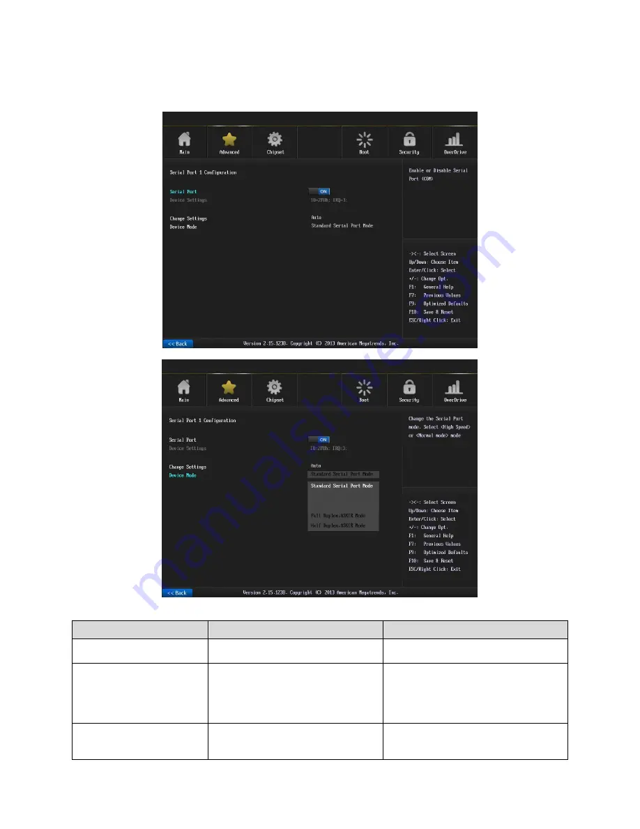
Page 38: ...iguration Item Options Description Serial Port Enabled Default Disabled Enable or Disable Serial Port COM Change Settings Auto Default IO 3F8h IRQ 4 IO 3F8h IRQ 3 4 5 6 7 10 11 12 IO 2F8h IRQ 3 4 5 6 7 10 11 12 IO 3E8h IRQ 3 4 5 6 7 10 11 12 IO 2E8h IRQ 3 4 5 6 7 10 11 12 Select an optimal setting for Super IO device ...

Page 39: ...rt COM Change Settings Auto Default IO 2F8h IRQ 3 IO 3F8h IRQ 3 4 5 6 7 10 11 12 IO 2F8h IRQ 3 4 5 6 7 10 11 12 IO 3E8h IRQ 3 4 5 6 7 10 11 12 IO 2E8h IRQ 3 4 5 6 7 10 11 12 Select an optimal setting for Super IO device Device Mode Standard Serial Port Mode Default Full Duplex ASKIR Mode Half Duplex ASKIR Mode Change the Serial Port mode Select High Speed or Normal mode mode ...

Page 40: ...abled Default Disabled Enable or Disable Parallel Port LPT LPTE Change Settings Auto Default IO 378h IRQ 5 IO 378h IRQ 5 6 7 10 11 12 IO 278h IRQ 5 6 7 10 11 12 IO 3BCh IRQ 5 6 7 10 11 12 Select an optimal setting for Super IO device Device Mode STD Printer Mode Default SPP Mode EPP 1 9 and SPP Mode Change the Printer Port mode ...

Page 41: ...Mode 3 6 2 8 HW Monitor The H W Monitor shows the operating temperature fan speeds and system voltages Item Option Description CPU Smart Fan Enable or Disable CPU Smart Fan T1 30 C Duty 55T2 40 C Duty 70T3 50 C Duty 80T4 60 C Duty 90risis 70 C Duty 100 PWM Output 0 100 Set CPU Fan Speed 3 6 2 9 WatchDog Configuration ...

Page 42: ...nute Watchdog Count Mode Selection Watchdog Timeout Value 0 Fill Watchdog Timeout Value 0 means disabled 3 6 2 10 AMI Graphic Output Protocol Policy Item Option Description Output Select Unknown Device Output Interface BIST Enable Disabled Default Enabled Starts or stops the BIST on the integrated display panel ...

Page 43: ... H81 User s Manual SEAX H81 User s Manual 43 3 6 3 Chipset Item Description South Bridge Configuration PCH Parameters North Bridge Configuration System Agent SA Parameters 3 6 3 1 South Bridge Configuration ...

Page 44: ...Item Options Description Primary Display Auto Default IGFX PEG PCIE Select which of IGFX PEG PCI Graphics device should be Primary Display Or select SG for Switchable Gfx Internal Graphics Auto Default Disabled Enabled Keep IGD enabled based on the setup options GTT Size 1MB 2MB Default Select the GTT Size Aperture Size 128MB 256MB Default 512MB Select the Aperture Size DVMT Pre Allocated 32M 64M ...

Page 45: ...imeout 1 65535 Number of seconds to wait for setup activation key 65535 0xFFFF means indefinite waiting Bootup NumLock State On Default Off Select the keyboard NumLock state Full Screen Logo Disabled Enabled Default Enables or disables Quiet Boot option UEFI Boot Auto Default Enabled Disabled Auto If the 1 st boot HDD is GPT then enable UEFI boot options otherwise disable Enabled Enable all UEFI b...

Page 46: ...unch Default UEFI only Legacy only The Launch PXE OpROM policy can t work at UEFI mode But it can work normally under Legacy mode Launch Storage OpROM policy Do not launch UEFI only Legacy only Default Controls the execution of UEFI and Legacy Storage OpROM Launch Video OpROM policy Do not launch UEFI only Legacy only Default Controls the execution of UEFI and Legacy Video OpROM Other PCI device R...

Page 47: ...ord 3 6 5 1 Administrator Password This setting specifies a password that must be entered to access the BIOS Setup Utility If only the Administrator s password is set then this only limits access to the BIOS setup program and is only asked for when entering the BIOS setup program By default no password is specified ...

Page 48: ...nual 48 SEAX H81 User s Manual 3 6 6 Performance 3 6 6 1 CPU Configuration Item Options Description Non Turbo Ratio Override 0 21 Default Non Turbo Ratio Override IA Core Current Max 1 8 Amp 0 IA Core Current Max 1 8 Amp ...

Page 49: ...ed Intel SpeedStep Technology Graphics Core Ratio Limit 0 10 Default Graphics Core Ratio Limit 3 6 6 2 North Bridge Configuration Item Options Description Performance Memory Profiles Automatic Default Manual XMP Profile 1 XMP Profile 2 The selection of Performance Memory Profiles which impacts memory sizing behavior ...

Page 50: ...tion Item Options Description Memory Voltage I O 1 50V Default 1 55V 1 60V 1 65V Set memory voltage SVID Override Voltage Target mV 0 SVID Override Voltage Target up to 2500mV CPU Voltage Offset mV 0 CPU Voltage Offset 0mV 998mV GT Voltage Offset mV 0 GT Voltage Offset 0mV 998mV ...

Page 51: ...H81 User s Manual SEAX H81 User s Manual 51 4 Drivers Installation Note Installation procedures and screen shots in this section are for your reference and may not be exactly the same as shown on your screen ...

Page 52: ...s automatically If not locate Index htm and choose the product from the menu left or link to Driver_Chipset Intel SEAX H81 Note The installation procedures and screen shots in this section are based on Windows 7 operating system Step 3 Select Install Step 1 Select Next to continue installation Step 4 Select Finish to complete Installation Step 2 Select Accept to the next step ...

Page 53: ...cally If not locate Index htm and choose the product from the menu left or link to VGA SEAX H81_VGA Note The installation procedures and screen shots in this section are based on Windows 7 operating system Step 3 Select Next to continue installation Step 1 Select Next to start setup Step 4 Select Next Step 2 Select Yes to the next step Step 5 Select Finish to complete Installation ...

Page 54: ...x page of Avalue s products automatically If not locate Index htm and choose the product from the menu left or link to Driver_Gigabit Realtek RTL8111E SEAX H81_LAN Note The installation procedures and screen shots in this section are based on Windows 7 operation system Step 3 Click Finish to complete setup Step 1 Click Next to Install Step 2 Click Install to begin the installation ...

Page 55: ...ts automatically If not locate Index htm and choose the product from the menu left or link to Driver_Audio Realtek ALC662 SEAX H81_Audio Note The installation procedures and screen shots in this section are based on Windows 7 operation system If the warning message appears while the installation process click Continue to go on Step1 Click Next to Install Step 2 Select Finish to complete Installati...

Page 56: ...ocate Index htm and choose the product from the menu left or link to Utility SEAX H81_USB3 0 Note The installation procedures and screen shots in this section are based on Windows 7 operating system Step 3 Select Next to continue installation Step 1 Select Next to start setup Step 4 Select Next to continue installation Step 2 Select Yes to the next step Step 5 Select Finish to complete Installatio...

Page 57: ...automatically If not locate Index htm and choose the product from the menu left or link to Utility SEAX H81_ME Note The installation procedures and screen shots in this section are based on Windows 7 operating system Step 3 Select Next to continue installation Step 1 Select Next to start setup Step 4 Select Finish to complete Installation Step 2 Select Yes to the next step ...

Page 58: ...SEAX H81 User s Manual 58 SEAX H81 User s Manual 5 Mechanical Drawing ...

Page 59: ...SEAX H81 User s Manual SEAX H81 User s Manual 59 Unit mm ...

Page 60: ...SEAX H81 User s Manual 60 SEAX H81 User s Manual Unit mm ...

Reviews: