background image

Quick  Reference  Guide 

LPC-1231/1531  Quick  Reference  Guide    11 


1.5.2 

LPC-1531 Front and Rear side 


(Unit: mm) 

Summary of Contents for LPC-1231

Page 1: ...A0R LPC 1231 1531 12 1 15 Intel Celeron SoC N3000 family Processor Fanless Rugged Touch Panel PC Quick Reference Guide 1st Ed 21 September 2015 Copyright Notice Copyright 2015 Avalue Technology Inc AL...

Page 2: ...HE USER WILL BE REQUIRED TO CORRECT THE INTERFERENCE AT HIS OWN EXPENSE Notice This guide is designed for experienced users to setup the system within the shortest time For detailed information please...

Page 3: ...be reasonably expected to cause the failure of the life support device or system or to affect its safety or effectiveness A Message to the Customer Avalue Customer Services Each and every Avalue s pro...

Page 4: ...stem Overview 8 1 4 1 Top View 8 1 4 2 Bottom View 8 1 5 System Dimensions 10 1 5 1 LPC 1231 Front and Rear side 10 1 5 2 LPC 1531 Front and Rear side 11 2 Hardware Configuration 12 2 1 LPC 1231 1531...

Page 5: ...charge before touching the CPU card Modern electronic devices are very sensitive to static electric charges As a safety precaution use a grounding wrist strap at all times Place all electronic compon...

Page 6: ...h EETI System Board EBM BSW Processor Intel Pentium Celeron processor I O Chipset Nuvoton NPCE388N System Memory 1 x 204 pin DDR3L 1600MHz up to 8GB Watchdog Timer H W Reset 1sec 65535sec 1sec step H...

Page 7: ...ATX is default setting Adapter Input 100 240Vac 50 60Hz Output 60W Adapter 12V 5A Adapter Mechanical Environment System Fan Fanless Construction Front Silver Aluminum Construction Rear Black Dimension...

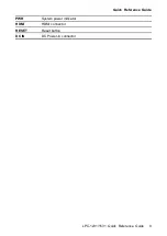
Page 8: ...View LPC 1231 LPC 1531 1 4 2 Bottom View LPC 1231 LPC 1531 Connectors Label Function Note POWER Power on button COM1 2 Serial port 1 2 connector DB 9 male connector LINE OUT Line out audio jack USB 4...

Page 9: ...Quick Reference Guide LPC 1231 1531 Quick Reference Guide 9 PWR System power indicator HDMI HDMI connector RESET Reset button DC IN DC Power in connector...

Page 10: ...LPC 1231 1531 10 LPC 1231 1531 Quick Reference Guide 1 5 System Dimensions 1 5 1 LPC 1231 Front and Rear side Unit mm...

Page 11: ...Quick Reference Guide LPC 1231 1531 Quick Reference Guide 11 1 5 2 LPC 1531 Front and Rear side Unit mm...

Page 12: ...1 12 LPC 1231 1531 Quick Reference Guide 2 Hardware Configuration For advanced information please refer to 1 EBM BSW User s Manual Note If you need more information please visit our website http www a...

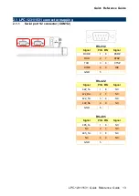
Page 13: ...2 1 1 Serial port 1 2 connector COM1 2 RS 232 Signal PIN PIN Signal DCD 1 6 DSR RXD 2 7 RTS TXD 3 8 CTS DTR 4 9 RI GND 5 RS 422 Signal PIN PIN Signal 422_Tx 1 6 NC 422_Rx 2 7 NC 422_Tx 3 8 NC 422_Rx...

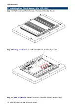
Page 14: ...stalling Hard Disk Memory For LPC 1231 Step 1 Unfasten 6 screws from the case Then take off the top chassis Step 2 Memory Installation Insert the SODIMM into the memory socket Step 3 1 SATA HDD Instal...

Page 15: ...nectors Just connect to SATA HDD with the two cables Step 3 2 Insert the HDD into the Drive Bay Remember to place the HDD down to the bottom exactly in order to screw the device tightly Step 4 Place b...

Page 16: ...Installing Hard Disk Memory For LPC 1531 Step 1 Unfasten 6 screws from the case Then take off the top chassis Step 2 Memory Installation Insert the SODIMM into the memory socket Step 3 1 HDD Installat...

Page 17: ...Guide 17 Step 3 2 Insert the HDD into the bracket and fasten 4 screws Step 3 3 SATA HDD Installation By default the SATA cables had been inserted to the according connectors Just connect to SATA HDD w...

Page 18: ...1231 1531 Quick Reference Guide Step 3 4 Insert the HDD into the Drive Bay Remember to place the HDD down to the bottom exactly in order to screw the device tightly Step 4 Place back the chassis with...

Reviews: