


HID-2138 User Manual
HID-2138 Quick Reference Guide
18
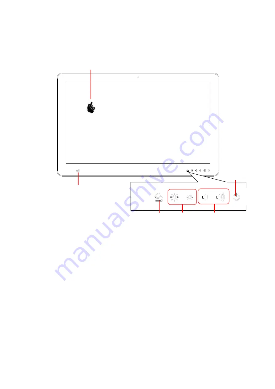
1.3 Front view
Note1:
Press this button for 2 sec to turn on or off LED reading light bar
Press this button for 4 sec to turn off or on for touch function
21.5” Touch Screen
NFC
Volume
Up/down
Brightness
Up/down
Power on/off
LED light bar/
Touch on/off*
Note1


