


8
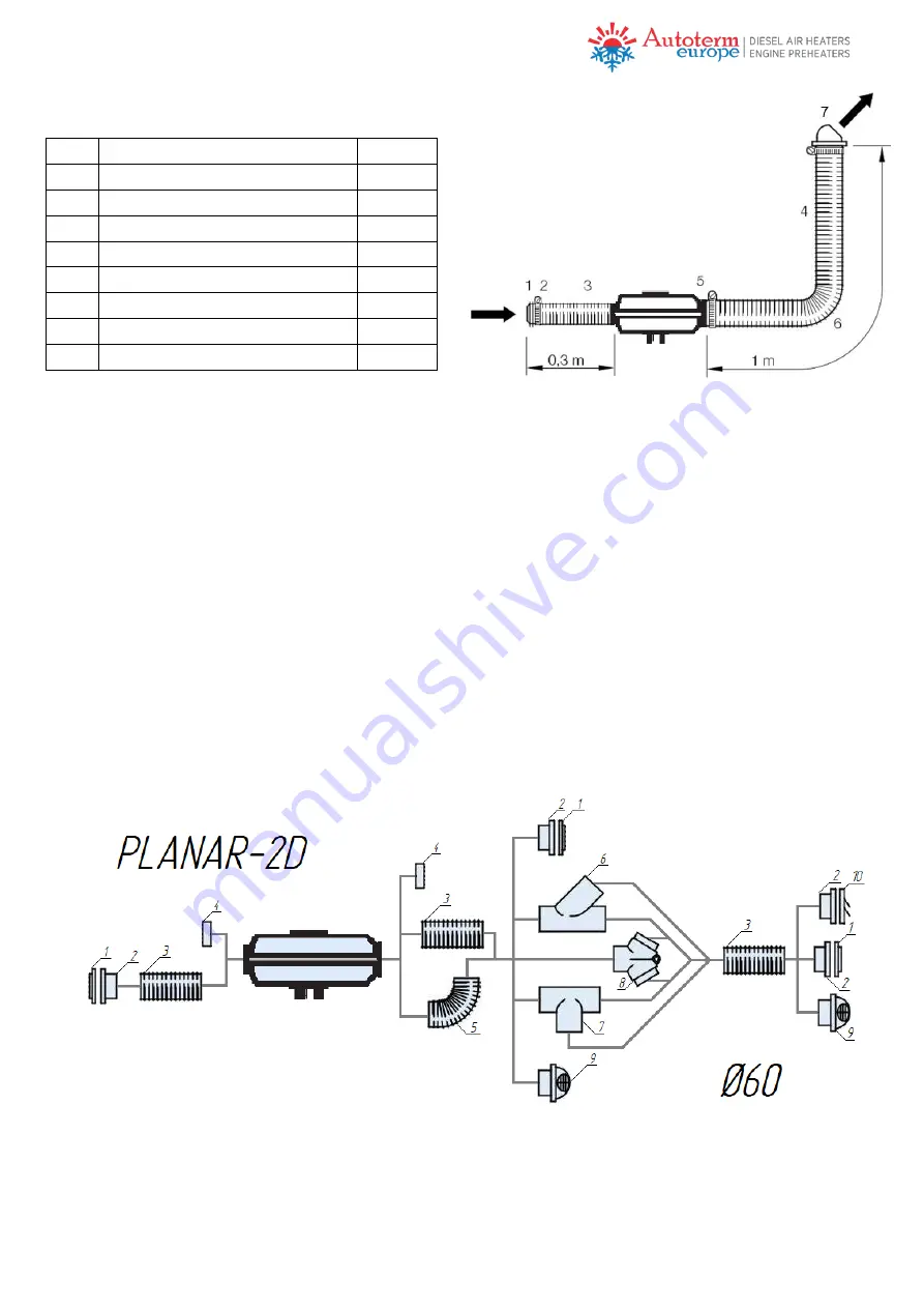
Table 2 – Example of calculating conductivity of
air duct
Nr Part
Coef
1
Grille Ø 60mm 30°
5
2
Clamp for air duct
0
3
Air pipe Ø60mm, 0.3m
3
4
Air pipe Ø60mm, 1m
10
5
Air outlet side
0
6
Air pipe Ø60mm, bend 90°
12
7
Adjustable grille Ø60mm
14
Total
44
Fig. 5 – Example of an installed air duct.
The heater is supplied with inlet and outlet grilles already installed. In such a case, the
heater can be used for heating of the room (cabin), in which it is installed. If several cabins
need to be heated, lay air ducts along the perimeter of the vessel. Replace the inlet and/or
outlet grille on the heater to connect the air duct to it (only for PLANAR-44D-12/24 and
PLANAR-2D-12/24). Use a flat screwdriver to disengage hitches on the heater casing and
remove the grille. Install an adapter (only for PLANAR-44D-12/24) and attach the air duct
to it with a clamp. Use different shape adapters and connectors for distribution of warm air
(it is recommended to use Y-shaped adapters to reduce resistance and increase
effectiveness, if possible). Install deflectors on ends of air ducts (Fig.6a for PLANAR 2D,
and Fig.6b for PLANAR 44D).
Do not deform channels with heated air. This may add additional resistance to the flow
of warm air and reduce efficiency of heating.
When distributing supply of hot air, one of deflectors MUST be of a non-closable type
to avoid overheating of the heater.
Fig. 6a – Air duct connections for PLANAR 2D


