

Installation Guide
P. 7
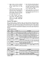
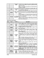
Throw Relay: this wire will connect to Pin 85 on the Relay,
and Pin 86 will be connected to the Ignition wire.
The Starter Kill output becomes active during remote starts.
One benefit of the Starter Kill is the Anti-Grind feature.
Once the vehicle has been remote started, the Anti-Grind
prevents the Starter Motor from re-engaging when the
Ignition Key is inserted in the Ignition Switch and
accidentally turned to the
CRANK
position.
8
ORANGE
N/A
This wire is not used.
9
PURPLE
(+) Siren or
Horn output
+12 V Siren output. Connect to the positive side of the
Siren.
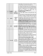
This wire provides a constant 500 mA ground output while
the System is running. This output becomes active at the
same time as the Ignition and shuts off when the System
shuts down, e.g.: when the Run Time has expired, when
the
STOP
button has been pressed, etc. This output can be
used to activate external relays, bypass kits, etc..
10
WHITE
(–) Ground
Out
When
Running
Caution!
If multiple relays or modules are connected to the
GROUND OUT WHEN RUNNING
wire, make sure they are
diode isolated from one another: feedback may otherwise
occur, causing damage to the vehicle.
This input should be used in vehicles with
negative-
switching
Door pins or Dome Light circuits. Connect to the
Dome Light wire that tests ground when a Door is open.
11
GREY
(–) Negative
Door input Caution!
The installer should use
either
the positive
or
the
negative Door input. Never use both of them
simultaneously.
12
YELLOW
(+) Glow-
Plug input
In Diesel Mode, this positive input will monitor the Glow
Plug Light: it will wait for up to 18 seconds until the Glow-
plug Light goes out before allowing the System to proceed
to cranking the Engine. Connect to the side of the Glow-
plug Light which is positive when the Light is on.
Note:
the System will nevertheless proceed to cranking the
Engine if the Glow-plug Light is still on after the 18-sec.
delay (25 sec. when the Run Time is set to 30 min.).
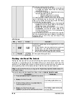
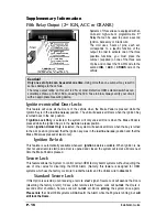
A Note on the Diesel Glow-plug Indicator Light:
(Also known as the “wait-to-start light”.) The purpose of the
Glow-plug circuit on diesel vehicles is to pre-heat the
Combustion Chamber before the vehicle is started.
When a Remote Starter is installed on a diesel vehicle, the
Glow-plug section of the Ignition circuit must be activated
and allowed to operate before the vehicle is remote-started.
For that purpose, the Glow-plug input wire of the System
must be connected to the Glow-plug indicator light of the
vehicle.
Caution!
The System will
only
accept
positive
Glow-plug
input signals, therefore negative Glow Plugs should only be
connected using relays to invert the polarity.
A diode must be added between the negative Glow-plug
trigger on the relay and the negative Glow-plug wire of the
car. This is to prevent feedback effects on the Glow-plug
indicator light on the instrument cluster: the light on the
dash would come on because of the feedback, even though
the circuit is off.