background image

6

CONSTANT IDENTIFICATION

5.2.3

UART Serial Communication

Serial communication in this project uses the FullDuplexSerial4portPlus v3

object. This object can support up to four full duplex serial ports, although
currently only one port is being used. The Propeller uses serial communication
to interface to several devices:

* Host computer via USB

* Wireless modem (such as Xbee)

* GPS

* Other microcontrollers

* UART sensors

When communicating with a host computer or other microcontrollers, the Pro-
peller uses the $ATXXX communications protocol described in 7.1.

6

Constant Identification

The quadrotor platform has a number of different constants that depend

on the hardware used. Most constants such as mass and rotor diameter are
relatively easy to measure. Other constants are not so easy. This section details
the more difficult constant identifications. For a full treatment of the math and
a list of all constants, see the Anzhelka mathematics document [3].

6.1

Thrust/Torque Test Stand Theory

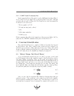
A good autonomous quadrotor needs to be able to measure, in real units

such as kilograms and seconds, important aspects about itself such as orienta-
tion, motor thrust, acceleration, and so on. It’s fairly easy to make a remote
controlled quadrotor platform since the human in the loop can intuitively correct
for many small errors, and our eyes are very good at collecting the necessary
raw information. An autonomous quadrotor does not have this luxury, and
must explicitly define each kinematic and dynamic equation. Among others,
the quadrotor must know the propeller torque and thrust constants.

K

T

=

T

ρn

2

D

4

(6.1)

K

Q

=

Q

ρn

2

D

5

(6.2)

Above, we have the two equations that define how the propellers affect our

quadrotor system. These equations can be found in context in the Anzhelka
Project quadrotor mathematics document ([3]). The form that 6.1 and 6.2 are
in now makes it convenient for us to measure the constants

K

T

and

K

Q

: if we

25

Summary of Contents for Anzhelka

Page 1: ...ter ilukester anzhelka com May 29 2012 And when he Herod had apprehended him Peter he put him in prison and delivered him to four quaternions of soldiers to keep him intending after Easter to bring hi...

Page 2: ...ses on the practical aspects of quadrotor flight For a theoretical treatment see the Anzhelka project mathematics document 3 Revisions Current project status and files can be found at blog anzhelka co...

Page 3: ...Guiding Vision 11 2 2 Assumptions 12 2 3 Realistic Constraints 12 2 4 System Environment and External Interfaces 12 2 5 Budget and Cost Analysis 12 2 6 Safety 13 2 7 Importance of Team Work 13 3 Syste...

Page 4: ...User Interface 28 8 1 Anzhelka Terminal 28 9 Testing 29 9 1 Hardware Testing 29 9 1 1 Frame 29 9 1 2 Motors Propellers 30 9 1 3 PCBs 30 10 Maintenance Plan 31 10 1 For the next ten weeks 31 10 2 For...

Page 5: ...d altitude With a suitable pilot or software behind the controls one can do amzing aerial acrobatics with the quadrotor Quadrotors are very similar to helicopters so what advantages do quadrotors have...

Page 6: ...is attached The tracking device will have its own GPS and IMU in order to be able to determine the location and heading of the subject object The quadrotor is intended to fly autonomously ie without...

Page 7: ...nly one team member has any experience with designing PCBs and circuits but not nothing to the extent of this project We believe that based on the work we have put into the project that we have earned...

Page 8: ...ion 10 1 1 5 Background and Prior Art There are many different quadrotor designs available but relatively few open source quadrotors The most noticeable are the AeroQuad 16 and the Ar ducopter 17 Most...

Page 9: ...ule the latter case would have a main type method and would be self supporting when running on the Propeller tool holds all the relevant development tools for that language BSTC for Spin for example c...

Page 10: ...velopment cycle a simple compilation script was devel oped A template form of this script can be found in software spin tool bst template sh This script will compile the Spin pro gram and if no errors...

Page 11: ...cronyms AT Anzhelka Terminal ATxxx Anzhelka Terminal Communication String BSTC Brad s Spin Tool Compiler EEPROM Electrically Erasable Programmable Read Only Memory ESC Electronics Speed Controller GUI...

Page 12: ...re around 15 minutes so average current drain is likely less The system is also constrained by the maximum acceleration and maximum rotation speed of the propellers Typically the propeller will not ro...

Page 13: ...must take extreme cautions in order to ensure the safety of everyone Autonomous systems are particularly dangerous because there is human behind the controls of the system and can become unpredictabl...

Page 14: ...are Introduction This section describes the quadrotor software environment 4 1 Propeller For this project we selected the Parallax Propeller as our main embedded processor This chip has several unique...

Page 15: ...ption is the built in video generation hardware that assists in creating NSTC PAL or VGA signals To make development easier for the programmer Parallax hosts a source code website that provides code f...

Page 16: ...objects are used for interfacing with external devices For example a typical Spin program might have an object for serial communication an object for VGA signal generation and an object for I2C commun...

Page 17: ...ibrary 15 The Float32 documentation includes timings and space requirements for each of the mathematical functions If we count the operations required for each block we can then calculate an estimate...

Page 18: ...ry for 496 longs If we break it into sections then the altitude and motor calculations will fit into a single cog but the moment block is too big Some optimizations will probably be able to reduce the...

Page 19: ...effective and in fact worse than nothing at all 11 Diagrams for the frame components have been included in the appendices and are also available at 1 5 1 2 Motors Propellers Since neither one of the t...

Page 20: ...up and down Figure 7 Volts vs RPM under no load As you can see that the current is linear with the voltage 5 1 3 Power Board PCB For this project we developed a custom circuit board to power the quadr...

Page 21: ...ing able to produce something that will be small enough to fit on your platform and large enough for you to solder the components onto The PCB design for the prototype took over a month to layout and...

Page 22: ...ucted out of wood and metal Ev erything was hand crafted A few components needed machining and those were done in a machine shop We developed the test stand from scratch with very little prior work to...

Page 23: ...re pulsed in a specific order The timing of the pulses determine the speed of the motor and the pulses must match the position of the motor rotor Modern brushless motor controller chips ESCs Electroni...

Page 24: ...tforward The two single wires from the Eagle Tree are connected to any two leads of the brushless motor Connecting only one lead would still allow the sensor to function but it results in slightly lar...

Page 25: ...full treatment of the math and a list of all constants see the Anzhelka mathematics document 3 6 1 Thrust Torque Test Stand Theory A good autonomous quadrotor needs to be able to measure in real unit...

Page 26: ...on a scale In a same way as thrust the force pressing on the scale can be read and with the length of the lever arm torque can be calculated Our test can measure thrust and torque simultaneously and a...

Page 27: ...e string lists below 7 1 2 Example Usages This protocol is used in the thrust torque test stand The test stand mea sures the thrust and torque using force sensors and measures the rotations per second...

Page 28: ...and to allow for parameter tuning AT is written in Python and uses the WxWidgets Python branch WxPython for the GUI AT is cross platform The AT GUI was written in WxPython and developed in part with t...

Page 29: ...ATXXX string Note this feature is still in development This table is generated at runtime so it is easy to change the number of motors and the motor parameters This was done in particular to support...

Page 30: ...wer that will have to travel through your traces that you have designed onto your board If you are trying to push 10 amps through a 6mil trace you are going to melt the trace and ruin your board Desig...

Page 31: ...senior design project is no where it needs to be as for a finished product and will require a lot more time to get there In the following weeks we hope to accomplish the following tasks Write motor PI...

Page 32: ...ch time as we have in our project Once the project is accepted by the open source community it should become self sustaining by volunteers Most likely these volunteers will come from the Parallax foru...

Page 33: ...experience Functionality is divided into tabs for easy access The motors tab allows for intuitive control of the graph and the motor table is clear and easy to understand The thrust torque test stand...

Page 34: ...ave created an identity for the project in the form of the name Anzhelka and our phoenix logo With these accomplish ments we are only a few small steps away from flying We were and are constantly surp...

Page 35: ...http forums parallax com showthread php 127372 PWM_32_V2 Question about Resolution constant 11 Vibration Loosening of Bolts and Threaded Fasteners 2012 http www boltscience com pages vibloose htm 12 E...

Page 36: ...s Texas Instraments Samples Microchip Samples Jack Mcbroom Other 15 Appendices Include the following Mathematics for quadrotors written for simpletons Source code printed in the 2 pages per page forma...

Reviews: