5.2
Software
5
QUADROTOR PROTOTYPE CONSTRUCTION
single motor. The sensor converts the brushless motor signals to a series of
pulses where each pulse is proportional to a rotation. The Propeller does not
measure the signal directly from a brushless motor control line because there
are very high voltages and back EMF from the motor which creates a very nasty
environment for the 3.3v microcontroller.
The Propeller object for this sensor is based on code provided by Tim Moore
[10] . For this project, interface modifications to the object were made to the
code in order to permit the reading of rotations per second. The object can
support up to eight brushless motor sensors.
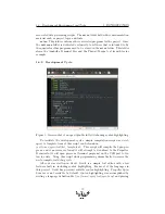
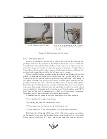
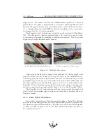
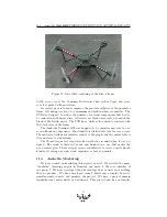
(a) The Eagle Tree brushless RPM sensor
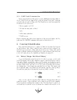
(b) Motor connection of the sensor.
Figure 11: The Eagle Tree sensor
Connection of the Eagle Tree sensor is straightforward. The two single wires
from the Eagle Tree are connected to any two leads of the brushless motor.
Connecting only one lead would still allow the sensor to function, but it results
in slightly larger errors (15 rps errors, instead of 10 rps errors with both). On
the microcontroller side the black line goes to 3.3V, red to Gnd, white to the
Propeller I/O pin. Despite going against standard color coding conventions, the
red line is connected to ground and the black is to 3.3v (the Propeller VDD).
The Propeller object for interfacing with the sensor counts the number of
clock cycles between rising edges of a pulse, and uses this to calculate the rota-
tions per second.
5.2.2
Pulse Width Modulation
Pulse width modulation is the technique of toggling a digital I/O pin high
and low in a repeating pattern. We use PWM in this project to interface the
the electronic speed controllers (ESC). The ESCs use servo type PWM signals:
a 1000 us to 2000 us pulse every 20 ms. The width of the pulse is relative to
the commanded speed.
24

