Autonics ADIO-EI Product Manual Download Page 2

-|Transparent Guide|-

Configuration of ADIO-EI

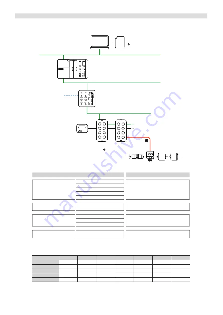
The figure below shows the EtherNet/IP network and the devices that compose it.
For proper use of the product, refer to the manuals and be sure to follow the safety considerations in the manuals.
Download the manuals from the Autonics website.

Operation mode

Fault State

 01)

Validation

Data Storage

Input Filter 

01)

Vendor ID

Device ID

Cycle Time

Digital Input

-

-

-

-

-

-

Digital Output 

-

-

-

-

-

-

IO-Link Input 

-

-

IO-Link Output 

-

-

IO-Link Input/Output

-

-

 01)  Unsupported on the atIOLink


■ The configuration instance and class

STEP

Reference manual

Hardware installation

Install and ground the ADIO 

ADIO-EI Product Manual

Connect the ports of ADIO

Supply power to the ADIO

IO-Link device settings

Set parameters and functions 

of IO-Link device

atIOLink User Manual

EtherNet/IP Master

ADIO-EI

Integrate the ADIO-EI to EtherNet/IP project

ADIO-EI (Studio 5000 Logix Designer Guide) 

01)


Set the ports of ADIO-EI

Checking the operation

Check the indicators

ADIO-EI Product Manual

01)  The project planning software of the upper level communication system may be different depending on the user’s environment. 


For more information, refer to the manufacturer’s manual.

Project planning software  + EDS file

 at IODD file

ADIO-EI

: EtherNet/IP Slave (Adapter),

    IO-Link Master

Power supply

IO-Link device

EtherNet/IP Switch

EtherNet/IP Master (Scanner) 

Ethernet / Fieldbus

Summary of Contents for ADIO-EI

Page 1: ... modify the unit Failure to follow this instruction may result in fire 06 Do not touch the product during operation or for a certain period of time after stopping Failure to follow this instruction may result in burn Caution Failure to follow instructions may result in injury or product damage 01 Use the unit within the rated specifications Failure to follow this instruction may result in fire or ...

Page 2: ...tion Install and ground the ADIO ADIO EI Product Manual Connect the ports of ADIO Supply power to the ADIO IO Link device settings Set parameters and functions of IO Link device atIOLink User Manual EtherNet IP Master ADIO EI Integrate the ADIO EI to EtherNet IP project ADIO EI Studio5000LogixDesignerGuide 01 Set the ports of ADIO EI Checking the operation Check the indicators ADIO EI Product Manu...

Page 3: ... 4 1 TX Transmit Data 2 RX Receive Data 3 TX Transmit Data 4 RX Receive Data Power supply port OUT 7 8 Socket Female IN 7 8 Plug Male Pin Function Description 1 2 3 4 5 5 4 3 2 1 1 2 0 V Sensor and actuator supply 3 F G Frame ground 4 24 VDCᜡ Sensor supply 5 24 VDCᜡ Actuator supply PDCT port M12 Socket Female A coded Pin Function 1 4 5 3 2 1 Not Connected N C 2 Data 3 0 V 4 Not Connected N C 5 Dat...

Page 4: ...ide 20 38 29 6 4 7 1 3 6 3 215 1 3 8 35 33 4 24 26 5 26 5 26 5 35 26 30 5 Ø4 5 M4 X 0 7 Ø4 5 M12 X 1 X 11EA 7 8 X 2EA 66 203 35 Dimensions Unit mm For the detailed dimensions of the product follow the Autonics website ...

Page 5: ... Prepare a flat or metal panel in the enclosure 02 Drill a hole to mount and ground the product on the surface 03 Turn off all power 04 Fix the product using M4 screws in the mounting holes Tightening torque 1 5 N m M4 M4 Installation UnitDescriptions 1 2 3 2 4 4 5 5 6 7 9 10 8 01 Grounding hole 02 Mounting hole 03 Insertion part for the name plate 04 Ethernet port 05 Power supply port 06 PDCT por...

Page 6: ...y settings 192 168 2 3 Static IP Address 001 to 255 The IP address of the Ethernet port Set the last octet of the IP address 192 168 2 BOOTP 800 to 899 The IP address is assigned by the Bootstrap Protocol BOOTP server IP Address Subnet Mask etc DHCP 900 to 999 The IP address is assigned by the DHCP server IP Address Subnet Mask etc 02 Turn on the ADIO EI again 03 Check that green LED of the US ind...

Page 7: ...Function Connector 2 Pin no Connector 2 Function 1 N C 1 5 VDCᜡ 2 Data 2 Data 3 0 V 4 0 V 4 N C 5 Data 3 Data 01 Connect to the EtherNet IP 01 Connect the M12 connector to the Ethernet port See the connections below 1 2 3 4 1 TX Transmit Data 2 RX Receive Data 3 TX Transmit Data 4 RX Receive Data 02 Connect the connector to the EtherNet IP network Network device PLC or EtherNet IP device supportin...

Page 8: ... 24 VDCᜡ Sensor supply 5 24 VDCᜡ Actuator supply 1 2 3 4 5 5 4 3 2 1 PWR OUT PWR IN PortConnections 03 Connect with the atIOLink Do not use the PDCT port and the Ethernet port at the same time 01 Connect the M12 connector to the PDCT port See the connections below 1 4 5 3 2 1 Not Connected N C 2 Data 3 0 V 4 Not Connected N C 5 Data 02 Connect the connector to the network device Network device PC ...

Page 9: ...ress Flashing Device self testing Power Green ON The connection is established Flashing No connection Red ON IP address conflict Another device has the same IP address Flashing Connection timeout 06 Ethernet connection Indicator LED color Status Description L A1 L A2 Green OFF No Ethernet connection ON The Ethernet connection is established Yellow Flashing Data transmission 07 Transmission rate of...

Page 10: ...or current US 9 A Dimensions W 66 H 215 D 38 mm Material Zinc Die casting Ethernet port M12 Socket Female 4 pin D coded Push Pull Number of ports 2 IN OUT Supported function daisy chain Power supply port Input 7 8 Plug Male 5 pin Output 7 8 Socket Female 5 pin Number of ports 2 IN OUT Supported function daisy chain PDCT port M12 Socket Female 5 pin A coded Push Pull Number of ports 1 Connection me...

Reviews: