-|Transparent Guide|-
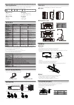
Replacing Relay
1. Disassemble a relay by using Two Way Ejector for relay replacement inside the product.
For TAKAMISAWA(Fujitsu)
relay
For MATSUSHITA
(Panasonic) relay
[Two Way Ejector]
Two Way
Ejector
location
2. After checking the location of the relay socket, insert the relay to be replaced.
[Disassembling relay using Two Way Ejector]
[Inserting
relay
]
Crimp Terminal Specifications
•
Unit: mm, Use the UL approved crimp terminal.
≥4.1
≤16.0
≥3.0
≤5.9
≥4.1
≤16.0
≥3.0
≤5.9
Fork crimp terminal
Round crimp terminal
❶ Connector
type
S: Screw
H: Hirose connector
❸ Relay
type
TN: TAKAMISAWA(Fujitsu) NYP
PA: MATSUSHITA(Panasonic) PA
❷ Number of
relay
04: 4-point
16: 16-point
32: 32-point
❹ Input logic
C: COM None
N: NPN (+COM)
P: PNP (-COM)
Ordering Information
This is only for reference, the actual product does not support all combinations.
For selecting the specified model, follow the Autonics website.
ABS -
❶ ❷ ❸
-
❹ N
Specifications
Model
ABS-S04
□
-CN
ABS-H16
□
-
□
ABS-H32
□
-
□
Applied relay
01)
PA: APAN3124 [MATSUSHITA (Panasonic)] / TN: NYP24W-K [TAKAMISAWA (Fujitsu)]
Output method
1a
1a
1a
Power supply
≤ 24 VDCᜡ ±10 %
≤ 24 VDCᜡ ±10 %
≤ 24 VDCᜡ ±10 %
Current
consumption
PA: ≤ 8 mA
02)
TN: ≤ 8.5 mA
02)
PA: ≤ 8 mA
02)
or ≤ 13 mA
03)
TN: ≤ 8.5 mA
02)
or ≤ 13.5 mA
03)
Rated load voltage &
current
04) 05)
250 VACᜠ 3A,
30 VDCᜡ 3A
250 VACᜠ 3A,
30 VDCᜡ 3A
250 VACᜠ 2A,
30 VDCᜡ 2A
No. of connector pins
-
20
40
Connector for
controller side
-
20-pin Hirose
(HIF3BA-20PA-2.54DSA)
40-pin Hirose
(HIF3BA-40PA-2.54DSA)
No. of relay points
4
16
32 (8점/1COM)
Terminal type
Screw
Screw
Screw
Terminal pitch
7.62 mm
7.62 mm
7.62 mm
Indicator
Operation indicator: blue
Power indicator: red,
operating and disconnection
indicator: blue
Power indicator: red,
operating and disconnection
indicator: blue
Varistor
None
None
None
Input logic
-
NPN / PNP model
NPN / PNP model
Material
CASE, BASE: MPPO,
terminal pin: brass
CASE: MPPO, BASE: PA66
(G25%), terminal pin: brass
CASE: MPPO, BASE: PA66
(G25%), terminal pin: brass
Approval
ᜢ ᜨ ᜫ
06)
ᜢ ᜨ ᜫ
06)
ᜢ ᜨ ᜫ
06)
Unit weight
(packaged)
PA: ≈ 68 g (≈ 104 g)
TN: ≈ 71 g (≈ 107 g)
PA: ≈ 224 g (≈ 307 g)
TN: ≈ 235 g (≈ 318 g)
PA: ≈ 345 g (≈ 438 g)
TN: ≈ 370 g (≈ 463 g)
01) For the detailed information about each relay, please refer to ‘Power Relay’ or data sheet from the manufacturer.
02) It is current consumption for a relay including LED current.
03) It is current consumption including LED current for power part to 2).
04) This value is rated with resistive load.
05) When connecting loads to output part, please connect loads of same power type.
Connecting loads of different power type may cause safety issues.
06) 30 VDCᜡ of rated load voltage is not subjected to UL Listed.
Applicable wire
- stranded
AWG 22-16 (0.30 to 1.25 mm²)
Tightening torque
0.5 to 0.6 N·m
Insulation resistance
≥ 1,000 MΩ (500 VDCᜡ megger
)
Dielectric strength
(coil-contact)
3,000 VACᜠ 50/60 Hz for 1 minute
Dielectric strength
(same polarity contact)
PA: 1,000 VACᜠ 50/60 Hz for 1 minute
TN: 750 VACᜠ 50/60 Hz for 1 minute
Vibration
0.75mm amplitude at frequency of 10 to 55Hz (for 1 min) in each X, Y, Z direction for 2 hours
Vibration (malfunction)
0.75mm amplitude at frequency of 10 to 55Hz (for 1 min) in each X, Y, Z direction for 10 min
Shock
500 m/s² (≈
50 G)
in each X, Y, Z direction for 3 times
Shock (malfunction)
147 m/s² (≈
15 G)
in each X, Y, Z direction for 3 times
Ambient temperature
-15 to 55 ℃, storage: -25 to 65 ℃ (no freezing or condensation)
Ambient humidity
35 to 85 %RH, storage: 35 to 85 %RH (no freezing or condensation)
Dimensions
•
Unit: mm, For the detailed drawings, follow the Autonics website.
■
4
-point
2-Ø4.5
78.8
78.8
72
70
32
35 mm DIN RAIL
5.5
38
■
16
-point
, 32
-point
16
-point
32
-point
A
140
173
B
70
100
C
70
100
A
B
4-Ø4.5
72 70
78.8
85.8
37
5.5
84
35 mm DIN RAIL
78.8
C
7.62 mm Pitch Jumper Bar
1. Using a nipper, cut the notches on the jumper bar as much as you need.
2. Loosen the screws which are needed to be common.
3. Insert the jumper bar under the loosen screws.
4. Tighten the screws.
7.62
3.2
0.8
2.7
9.5
10.9
N
Model
The number of
jumper pin
N
JB-7.62-04
4
29.5
JB-7.62-08 8
60.0
Installation
■ DIN Rail
•
Mounting
1. Pull the Rail lock on the rear of the product to the direction ①.
2. Hang DIN rail hook on the rear of the product onto DIN rail.
3. Push the product to the direction ②, and push the Rail lock to the direction ③ to fix onto
the DIN rail.
①
②
③
Rail lock
DIN rail hook
DIN rail
•
Removing
1. Insert a tool such as screwdriver into the hole of Rail lock.
2. Push the toll to the direction ① and pull the Rail lock.
3. Lift bottom of the product to the direction ② and remove the product from DIN rail.
①
Rail lock
②
■
Panel
Product with the mounting hole can be installed on panel with screw.
It is recommended to use M4×15 mm of spring washer screws.
If you use flat washer, its diameter should be Ø 6 mm.
Tighten the screw with the tightening torque of 0.7 to 1.0 N·m.


