background image

OWNERS COPY

WARNING

It is vital for the safety of persons to follow all 

instructions. Failure to comply with the installation

instructions and the safety warnings may result in

serious personal injury and/or property and remote

control opener damage. 

Please save these instructions for future reference.

Installation Instructions

AUTOMATIC TECHNOLOGY AUSTRALIA PTY LTD

GDO-6 v2 Slim-Drive EasyRoller

®

ROLL UP GARAGE DOOR OPENER

Summary of Contents for GDO-6 v2

Page 1: ... installation instructions and the safety warnings may result in serious personal injury and or property and remote control opener damage Please save these instructions for future reference Installation Instructions AUTOMATIC TECHNOLOGY AUSTRALIA PTY LTD GDO 6 v2 Slim Drive EasyRoller ROLL UP GARAGE DOOR OPENER ...

Page 2: ... person to ensure that a nominated person should confirm that the power operated door has been installed in accordance with the instructions provided by the door manufacturer and the installation instructions provided by ATA 3 as the responsible person to check after installation the operation of the power operated door 4 as the responsible person to test and verify the sensitivity of the unit whe...

Page 3: ...gs Technical Specifications Trouble Shooting Guide Parts List Warranty Supplier Installer Information 4 5 6 8 9 9 9 10 11 12 12 13 14 14 15 16 17 17 17 18 18 18 19 19 20 20 21 22 23 24 Automatic Technology Australia Pty Ltd to the extent that such may be lawfully excluded hereby expressly disclaims all conditions or warranties statutory or otherwise which may be implied by laws as conditions or wa...

Page 4: ...ance to the garage and a battery back up kit is not fitted to the opener a keyed cable release should be fitted to the exterior of the garage Warning It is vital for the safety of persons to follow all instructions Failure to comply with the following Safety Rules may result in serious personal injury and or property damage The unit should be installed so that it is protected from the elements It ...

Page 5: ...ing capacity of the opener is exceeded an audible beeper will sound to indicate that an overload has occurred AUTO COURTESY LIGHT The opener s courtesy light illuminates automatically whenever the door is activated The light can also be switched on and off without operating the door This is done by pressing the button on any transmitter which has been coded to operate the light The light will stay...

Page 6: ...button the time is increased Each press will increase the time by one second Pressing the close button will decrease the time ENGAGE DISENGAGEMENT CORD is used to switch the door into manual mode especially in case of a power failure The length of the string is also adjustable EASY ACCESS TRANSMITTER The manual release engage disengagement handle has a wireless transmitter within its housing If th...

Page 7: ...S LED YELLOW 6 CLOSE DRIVE BUTTON RED 7 CLOSE LIMIT LED RED 8 AUTO CLOSE TIME BUTTON 9 ENGAGE DISENGAGEMENT HANDLE INC EASY ACCESS TRANSMITTER 10 SET BUTTON ORANGE 11 O S C BUTTON YELLOW 12 FUSE 13 BATTERY CHARGER INPUT 14 OPEN DRIVE BUTTON GREEN 15 OPEN LIMIT LED GREEN 16 FORCE MARGIN SET BUTTON 17 PROGRAMMER INPUT 2 3 4 5 6 7 8 9 11 12 13 14 15 16 10 1 17 ...

Page 8: ...ANSMITTER PTX 4 2 PTX 4 WALL MOUNT BRACKET 1 ALKALINE BATTERY A23 12V 2 WEIGHT BAR NOT INCLUDED IN SOME MODELS 1 PAN HEAD SCREW M4x50mm NOT INCLUDED IN SOME MODELS 2 NILOCK HEX NUT M4 NOT INCLUDED IN SOME MODELS 2 FLAT WASHER I D 3 16 x 1 2 NOT INCLUDED IN SOME MODELS 2 SCREW 6x1 2 PLASTIC WALL PLUGS 2 LOCKING BAR COVERS 2 INSTALLATION MANUAL 1 ...

Page 9: ...ld not stick or bind in the guide tracks The ideal operational effort in raising or lowering the door should not exceed a force of 10kg 22 lbs Make sure that all door locks ropes chains etc are either released or disabled and remove unnecessary accessories 2 FIXING OF DOOR WEIGHT BAR Move the door manually to the mid open position Place the weight bar on the bottom rail in the middle of the door a...

Page 10: ...on metallic object e g pen to remove the battery Gently lever the battery out of the holder taking care to not damage the circuit board Fig 6 WARNING Metallic objects used to remove the battery may damage the circuit board or the battery REPLACING THE BATTERY Make sure that positive side is facing up Place one side of the battery into the holder Fig 7 then press the battery in and down firmly unti...

Page 11: ...door mounting bracket from wall 6 Remove the drive assembly from the packaging Try to rotate the drive gear by pushing on the fork If the gear does not rotate the manual mode has to be selected To select pull downward on the string handle then release slowly The drive gear should now rotate freely 7 Slide the drive assembly over the door axle making sure that the fork extends into and over one of ...

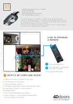
Page 12: ...12 move the door up by hand to an approximately mid open position 2 Re engage the drive gear to the door by pulling down on the string and then releasing 3 Press the Close button Fig 13 the door will start closing Release the button once you have reached your desired closed limit position Adjust close position with Open button if required 4 Press the Set button This action will store the closed li...

Page 13: ...ress will enable you to inch the door to your desired closed position Press button 1 to adjust position if necessary 8 Once you are happy with the position press button 2 this action will store into memory the closed limit position 9 Press button 1 the door will start opening Release the button once you are 1 to 2 cm from your desired open limit position 10 Press button 1 briefly Each press will e...

Page 14: ... panel cover for access Remember to replace the cover when set up is complete 9 3 TO INCREASE FORCE PRESSURE 1 Press and hold the Force Margin Set button Fig 16 2 While holding down the Force Margin button press the Open button Each press increases the force margin in both directions The Open Limit LED will illuminate each time the Open button is pressed Each press increases the force margin If th...

Page 15: ... PET PEDESTRIAN MODE 1 Press and hold Door Code button and the Close button Fig 19 2 Press the button on the transmitter you would like to use to control pet mode for two seconds pause for two seconds Press the same transmitter button again for two seconds 3 Release all buttons to store the transmitter in memory 4 Press the transmitter button to test if it operates the pet mode To change the defau...

Page 16: ...d now be stored 5 Wait for 10 seconds and then test the new transmitter to see if it operates the door 12 DELETING PROGRAMMED CODES 12 1 DELETING A STORED TRANSMITTER CODE 1 Select the transmitter you want to delete 2 Press and hold the Door Code button Fig 21 3 Press the transmitter button you would like to delete for two seconds Pause for two seconds Press the transmitter button again for two se...

Page 17: ...n and the auto close time has been set If the P E path is not broken the door will remain open till the path is broken If the Door Opener incurs an obstruction not from the P E while closing the door will re open and not auto close until the path of the P E beam is broken again SETTING AUTO CLOSE TIME 1 Press in and hold the Auto Close Time button Fig 22 2 While holding in the Auto Close Time butt...

Page 18: ...ttons to move the door to your required new pet open position 3 Press the Set button to record the new position The pet mode is activated from a transmitter button coded to that function see Step 10 3 on page 15 When activated the door drives to the preset position from either above or below If the pet button is pressed while the door is moving the door will be stopped If the pet button is pressed...

Page 19: ...cs Force Margin Set Auto Close Time then Close Each press of the open button decreases the light time by 10 secs Force Margin Set Auto Close Time then Set Reloads the factory set default light time Close for 6 Secs Clears the door limits set positions Limits then need to be reset Open for 6 Secs Door in Closed Position Enters pet pedestrian position adjustment mode Set then power on hold until all...

Page 20: ...PTX 4 TRANSMITTER BATTERY A23 Alkaline 12 Volts EAT 1 TRANSMITTER BATTERY CR1220 Lithium 3 Volts GLOBE Festoon Type 15W 24V DC FUSE 10A Slow Blow DEFAULT SETTINGS AND SPECIFICATIONS 20 Note 1 The maximum continuous curtain residential roll up door opening that the EasyRoller can be installed on is 5500mm wide by 2700mm high The door must be well balanced A person of average strength should be able...

Page 21: ...way Increase force margin setting See Step 9 3 on page 14 Or re calculate force margin See Step 9 6 on page 14 Remove obstruction Door operates from drive unit O S C button but not from transmitter See note Transmitter code not stored in memory Flat Battery Code transmitter in to openers memory Refer Step 10 1 on page 15 Replace battery A23 Alkaline 12V Door will not close fully Door limits positi...

Page 22: ...SPARE PARTS LIST 22 WHEN ORDERING SPARE PARTS PLEASE QUOTE THE ORDER CODE NUMBER TO YOUR INSTALLER DEALER ...

Page 23: ...dence of unauthorised repairs k any cost relating to damage caused by misuse negligence or failure to maintain the equipment in a proper working order as per clauses d through i l installation adjustment or use which is not in accordance with the instructions set out in installation instruction manual m attempted or complete modification or repairs to the product carried out by a person who is not...

Page 24: ...el 44 0 1780 758 528 Fax 44 0 1780 758 501 February 2006 Automatic Technology Australia Pty Ltd All Rights Reserved SecuraCode and EasyRoller are registered trademarks of Automatic Technology Australia In an ongoing commitment to product quality ATA reserve the right to change specifications without notice E OE Printed For Export Purchased From ___________________________________ Phone ___________...

Reviews: