


p 41/58
Technical Manual NAM-BL4x-MT-EN-C
The information in this document is the property of Automatic Systems and is confidential. The consignee withholds from using it for anything other than the use of the products or the execution of the
project to which they belong and withholds from communicating it to third parties without prior written agreement from Automatic Systems. Document subject to change without prior notice.
5. ADJUSTMENTS
The equipment was assembled, adjusted and tested at the factory in accordance with the configuration
required when the order was placed. Nevertheless, it must be checked before it is put in service the first time
and when there is a problem with the equipment's operation.
Any repairs to the equipment must be carried out in compliance with safety instructions listed in Ch. 1.
Notably,
the arm must be in the upright position (open) before working inside the housing
, in order to
decrease the spring compression and avoid untimely movements of the driving mechanism.
Ground cables connect all the metal parts to each other (Ch. 4.7.).
They must not be damaged at the time of disassembly and must be reconnected during reassembly.
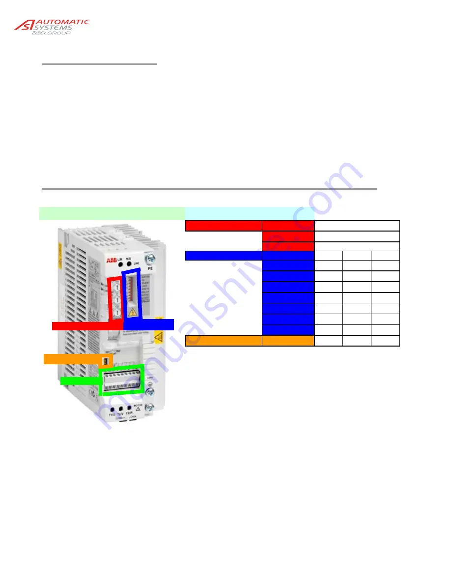
5.1. Setting the parameters for the variable speed controller
ABB ACS50 V1.35d
Parameters
Potentiometers
Motor I Name
150
ACC/DEC
0
HI Freq
Name
Selectors
Hz
50
60
Silent
OFF
ON
Load
P&F
CT
Jog Hz
*
5
10
Relay
FLT
RUN
AI Offset
OFF
ON
Autoreset
OFF
ON
HI Freq
OFF
ON
Analogue
AI
U
*
NOTE: For barrier longer than 4m ASA recommend to set the Jog at 10. See electrical diagram.
Note that the speed drive will only acknowledge the new parameter if a jumper is placed between the inputs “JOG”
and “+12V”. The jumper must be set in place prior to a power up. Once the procedure is done the jumper must be
removed for the speed drive to resume normal operation.
Potentiometers
Selectors
Inputs
Analogue


