Automated Logic M220NX Technical Instructions Download Page 6

Revised 4/3/00 • M220nx

6

© 2000 Automated Logic Corporation

• 0 to 5VDC: The output impedance of a 0

to 5VDC source must not exceed
10kohms. The input impedance of the
M220nx is approximately 1Mohm.

• 0 to 20mA: The input resistance on the

“A” input is 250 Ohms. The “B” terminal
supplies a voltage source to power the
4-20mA transducer. The “B” terminal is
capable of supplying 18 to 24VDC, but
the total current of both “B” terminals
must not exceed 40mA. If the voltage
measured from the “B” terminal to Gnd
is less than 18VDC, you need to use an
additional external power supply.

• Dry Contact: A 5VDC wetting voltage is

used to detect contact position. This
results in a 0.5mA maximum sense
current when the contacts are closed.

The M220nx accumulates up to ten input
pulses per second.

1. Be sure the M220nx’s power is off before

wiring any inputs or outputs.

2. Connect the input wiring to the screw

terminals on the module as shown in
Figure 4.

NOTE

If a 4-20 mA sensor uses an

external 24VAC power supply, connect

one leg of the 24VAC supply to the module
ground.

3. Set the configuration jumper for each

input to indicate the type of input used.
Make sure the jumper is positioned
correctly, and be sure to grip the jumper
by the sides only. See Figure 5 on page 7.

4. For each input, enter the channel number,

offset, and gain on the Function Block’s
Parameter page in SuperVision. Valid
channel numbers are listed in “Channel
Numbers” on page 7.

5. To verify each input’s operation, have

each sensor create a known value and

Table 2. Input wiring restrictions

Input

Maximum
Length

Minimum
Gauge

Shielding

0 to 5VDC

50 feet
15 meters

24AWG

shielded and
grounded to
module’s

B

or Gnd
terminal

Thermistor
Dry contact

50 feet
15 meters

24AWG

shielded and
grounded to
module’s

B

or Gnd
terminal

0 to 20mA

150 feet
46 meters

20AWG

unshielded

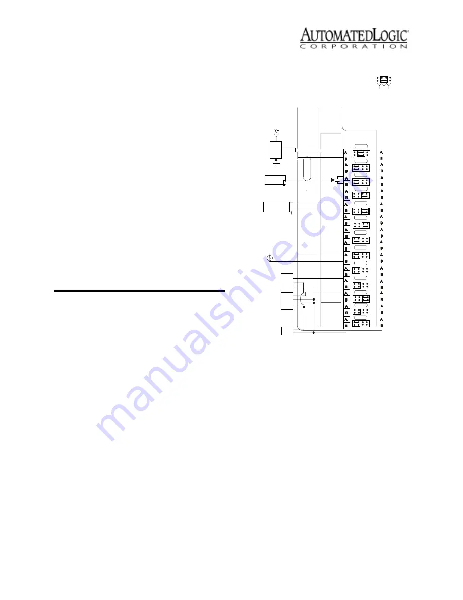
Figure 4. Input Wiring

PW R

PW R

PW R

OUT

OUT

GND

GND

GND

0-5VDC

DRY

CONTACT

PASSIVE

TRANSDUCER

4-20mA

12V or 24V

LOOP INPUT

THERMISTOR

3 WIRE
4-20mA

ISOLATED AC
or DC POWER

SUPPLY

4 WIRE
4-20mA

OUT +
OUT -

OUT +

OUT -

TO MODULE GND

Universal Input

Mode Select

0-

5

V

D

C

0

-20mA

Th
e

rm

ist

o

r

Dr
y

C

onta

c

t

Inputs
5V Max, 20mA Max

Summary of Contents for M220NX

Page 1: ...n BACnet is a registered trademark of ASHRAE All other brand and product names are trademarked by their respective companies Technical Instructions M220nx Using the M220nx 2 Specifications 3 Mounting 3 Addressing 3 Power Wiring 3 CMnet Communications 4 Using the M220nx on an ARC156 CMnet 4 Using the M220nx on a 9600 or 38 4K bps CMnet 4 To connect the M220nx to the CMnet 5 Communicating with the W...

Page 2: ...signed to provide reasonable protection against harmful interference when the equipment is operated in a commercial environment This equipment generates uses and can radiate radio frequency energy and if not installed and used in accordance with the instruction manual may cause harmful interference to radio communications Operation of this equipment in a residential area is likely to Figure 1 Modu...

Page 3: ...ention during power outages Listed by UL 916 PAZX cUL C22 2 No 205 M1983 PAZX7 FCC Part 15 Subpart B Class A Mounting Screw the M220nx into an enclosed panel using the mounting holes provided on the cover plate Be sure to leave about 2 inches 5 centimeters on each side for wiring Addressing Before setting or changing the address make sure the M220nx s power is off The M220nx only reads the address...

Page 4: ...t at 156 kbps The ARCNET CMnet configuration provides BACnet compatibility as well as better performance over a legacy CMnet All modules on a CMnet must communicate at the same speed When communicating at 156 kbps the CMnet uses a unique implementation of the industry standard ARCNET protocol called ARC156 For a summary of the differences between ARCNET and ARC156 please refer to the 156K CMnet Wi...

Page 5: ...o the EIA 232 port of the APT using a standard straight through serial cable 2 Set the APT s Mode Select switch On an ARC156 CMnet use the TTL setting On a legacy CMnet use the 485 setting 3 Connect the Access Port of the APT to the Access Port of the module 4 In SuperVision define the connection type using Table 1 Inputs The M220nx module has two universal inputs to accept the types of signals li...

Page 6: ...xternal 24VAC power supply connect one leg of the 24VAC supply to the module ground 3 Set the configuration jumper for each input to indicate the type of input used Make sure the jumper is positioned correctly and be sure to grip the jumper by the sides only See Figure 5 on page 7 4 For each input enter the channel number offset and gain on the Function Block s Parameter page in SuperVision Valid ...

Page 7: ...nel Numbers The following tables show the valid channel numbers for each point on the M220nx Enter the channel number offset and gain for each point in Eikon before the Function Block is made or on the FB s Parameter page in SuperVision If an offset and gain are not provided here use SuperVision s Point Configuration or Point Help feature to determine the offset and gain Figure 5 Jumper Position F...

Page 8: ...t the module to try to restore communication Formatting the module erases all memory so you need to transfer memory back to the module once it is formatted 1 Turn the module s power off Make sure the module s address switches are not set to 0 0 2 Press and hold the Format button see Figure 1 on page 2 for location 3 While continuing to hold the Format button turn the module s power on 4 Continue t...

Page 9: ...l Production Date To determine when a module was manufactured check the module status report for the module in SuperVision Refer to the SuperVision User s Guide for more information about the module status report A sticker on the back of the module also shows the date the module was manufactured The first three characters on the sticker indicate the type of module The next three characters show th...

Reviews: