background image

Revised 11/6/02 • LGRM-E

3

© 2002 Automated Logic Corporation

Specifications

Power

115VAC ±10%, 15W, 60Hz wall 

outlet adapter. 

Adapter Output

9VDC, 0.75A minimum, 

supplied. 

Auxiliary Device Power

24VAC ±10%, 

0.5A, 12VA, 60/50Hz.

Communications

LGnet Port with Ethernet 

10base-T (10Mbps). CMnet Connection  
with EIA-485, twisted pair, selectable for 
156 kbps, 38.4 kbps, or 9600 bps. One 
9-pin EIA-232 connector Console Port for 
direct connect or modem. One 5-pin 
connector Console Port for direct connect 
or modem. One Access Port for direct 
network using an APT. One Auxiliary 
Device Port (Keypad/Display Port).

Environmental Operating Range

0 to 

130°F (-17.8 to 54.4°C); 10 to 90% relative 
humidity, non-condensing. 

Status Indication

Visual (LED) status of 

CMnet, Console Ports and Ethernet 
communications, errors, running, and 
power.

Memory

256KB Flash, 512KB 

battery-backed static RAM.

Protection

Built-in surge and transient 

protection circuitry.

Listed By

UL 916 (PAZX), cUL C22.2 

No.205 - M1983 (PAZX7).

Mounting

The LGRM-E is rack-mounted using four 
holes on the faceplate (see Figure 1 on page 
2).
 If a rack is not available, the LGRM-E can 
be mounted with mounting brackets.

The LGRM-E is designed to be mounted inside 
the building. All warranties are void if 
mounted outside.

CAUTION 

 Changes or modifications to this 

unit not expressly approved by the party 
responsible for compliance could void the 
user’s authority to operate equipment.

Addressing

LGnet addressing

The LGRM-E has two rotary switches and a 
DIP switch used to assign the LGRM-E’s 
address. One rotary switch corresponds to the 
tens digit and the other corresponds to the 
ones digit. DIP switch six corresponds to the 
100s digit.

NOTE

SuperVision v2.6 and some gateways 

may not recognize an LGRM-E if the its 
address is higher than 60. However, LGRM-Es 
recognize peer gateways with addresses from 
1 to 199.    

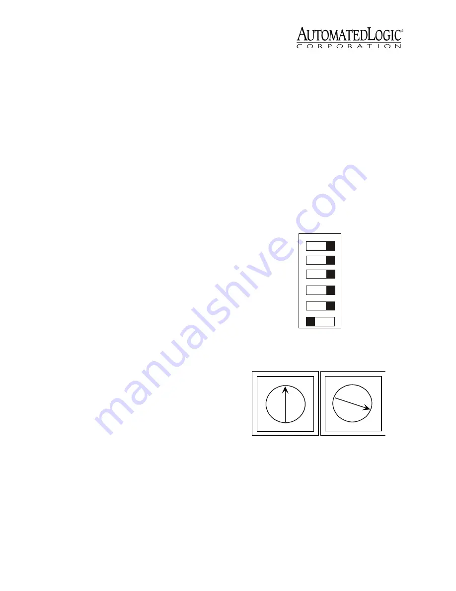
For example, if the LGRM-E’s address is 3, set 
DIP switch six to zero (see Figure 2), the tens 
rotary switch to zero, and the ones rotary 
switch to three (see Figure 3). 

 Figure 2. DIP Switches

 Figure 3. rotary Switches

9600/38.4k baud

9600/38.4k baud

9600/38.4k baud

Default/Assigned

Legacy/ARC156

100s

CMnet

Con 1

Con 2

IP ADD

Mode

0

Switch

Number

1

2

3

4

5

6

0

1

2

3

4

5

6

7

8

9

0

1

2

3

4

5

6

7

8

9

10's

1's

Summary of Contents for LGRM-E

Page 1: ...rOp is a trademark of Automated Logic Corporation BACnet is a registered trademark of ASHRAE All other brand and product names are trademarked by their respective companies Technical Instructions LGRM E Using the LGRM E 2 Specifications 3 Mounting 3 Addressing 3 LGnet addressing 3 IP Addressing 4 Wiring 5 Power Wiring 5 Communications Wiring 5 Initializing the LGRM E 6 Transferring Memory 7 Troubl...

Page 2: ...e Automated Logic website at www automatedlogic com or on the SupportPlus CD NOTE This equipment has been tested and found to comply with the limits for a Class A digital device pursuant to Part 15 of the FCC Rules These limits are designed to provide reasonable protection against harmful interference when the equipment is operated in a commercial environment This equipment generates uses and can ...

Page 3: ...s on the faceplate see Figure 1 on page 2 If a rack is not available the LGRM E can be mounted with mounting brackets The LGRM E is designed to be mounted inside the building All warranties are void if mounted outside CAUTION Changes or modifications to this unit not expressly approved by the party responsible for compliance could void the user s authority to operate equipment Addressing LGnet add...

Page 4: ...ocal network segment Assigned When the IP ADD DIP switch is set to Assigned you must set the above parameters on the LEM Parameter page Default mode Use the following procedure to set the IP address when using the Default mode 1 Set the IP ADD DIP switch to Default 2 Turn the LGRM E s power on 3 If using SuperVision v2 6 edit your HOSTS file to include the following line for each gateway see the T...

Page 5: ...nect power to the LGRM E 1 Turn off the LGRM E s power switch 2 Connect the terminal strip connector see Figure 4 to the power connector on the back of the LGRM E see Figure 5 on page 6 3 Plug the power adaptor into an outlet 4 Turn the module s power switch on When the module turns on the Run and Power LEDs turn on The Run LED begins blinking and the Error LED turns off See Table 3 on page 10 to ...

Page 6: ...ame polarity as used throughout the rest of the CMnet 3 Make sure the LGRM E is configured for the correct communication speed Connecting to the LGnet Connect a LAN 10base T cable to the Ethernet port Connecting to a Workstation or Modem Connect the DC95 or DC99 cable to console port 1 or 2 See Communicating with the Workstation on page 7 for more details NOTE The EIA 232 connection should not exc...

Page 7: ...ver and look at the module status report in SuperVision to make sure the module type and number agree with the module To view the module status report in SuperVision v3 0 click Tools Troubleshooting Module Status To view the module status report in SuperVision v2 6b press the Esc key type MO module address 15 and press Enter 3 Transfer memory to the module In SuperVision v3 0 click Tools Troublesh...

Page 8: ... Port 9 pin 20 DTR 7 GND 8 DCD 3 RX 2 TX Workstation 25 pin DCD 1 DTR 4 TX 3 RX 2 GND 5 Console Port 9 pin DS R 6 RI 9 CTS 8 RTS 7 8 DCD 20 DTR 2 TX 3 RX 7 GND Modem 25 pin 6 DSR 22 RI 5 CTS 4 RTS G ND 5 TX 1 RX 2 Console Port 5 pin 5 GND 2 RX 3 TX W orkstation 9 pin Console Port 2 DTR 3 20 DTR TX 1 2 TX RX 2 3 RX GND 5 7 G ND Console Port 5 pin DCD 4 8 DCD Modem 25 pin W ire connection usually no...

Page 9: ... on page 2 for location While continuing to hold the Format button turn the module s power on 3 Continue to hold the button until the Error LED flashes three times in sync with the Run LED 4 Release the Format button 5 Transfer memory to the module Refer to Transferring Memory on page 7 LEDs The LGRM E has several LED indicators to show the status of certain functions Table 3 on page 10 explains t...

Page 10: ...out the module status report A sticker on the back of the module also shows the date the module was manufactured The first three characters on the sticker indicate the type of module The next three characters show the year month and week of manufacture The month digit is in hexadecimal Table 3 LED Signals Run LED Error LED Condition 2 flashes per second Off Normal 2 flashes per second 1 flash per ...

Reviews: