background image

2

v5.3 25523

© 2005 Directed Electronics, Inc.

On cars with airbags, you may notice bright yellow tubes or harnesses
marked SRS (Supplemental Restraint System) underneath the steering
column area.  DO NOT tamper with these wires in any way, to prevent
personal injury and/or damage to the air bag system.

Battery gases are explosive.

Do not smoke while working near the car’s battery.

Note:  Some installers connect a battery charger to the vehicle’s battery during
installation.  This is fine, but it must be removed before running the vehicle under
remote starter control.

All General Motors (GM), rear wheel drive vehicles built prior to 1995
with automatic transmissions and Dodge Dakota trucks (4 cylinder
engines only) with automatic transmissions built prior to 1996 have a
MECHANICAL TYPE of NEUTRAL SAFETY SWITCH.  See important
warning on the last page of these instructions.

When running the wires through the car’s firewall, be sure to protect
them from sharp metal edges and  from hot surfaces on and around the
engine.

INSTALLATION INSTRUCTIONS

1.  Before You Start

Take time to read through the whole installation manual before beginning.

Always leave a window open to avoid locking your keys in your car.

IMPORTANT:  


  After having read the entire manual, start the installation

by putting the yellow WARNING STICKER in the engine compartment.
Choose a surface that is clean and readily visible when the hood is open.

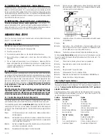
POWER & IGNITION HARNESS

The remote starter module will be installed under the dash once all wiring has been
completed.  

Do not mount the module at this time! You will need to check

the red diagnostic LED light as the installation progresses

.   


  Locate (or

drill) a hole in the firewall to run the PURPLE and GREEN wires of the 

Control

Harness

 and the PINK wire of the     

Power Harness

 into the engine compartment.

The remaining short wires stay in the passenger area. Leave about a foot of the wire
harness under the dash for ease of working and visual access to the diagnostic light.

The 

Installation Information

 section of www.designtech-intl.com is available 24

hours/day to provide you with free, up-to-date vehicle wiring information for your
particular vehicle.

Note:  Always connect the 

PINK 

and 

BLACK 

wires before connecting any of the other

wires. Do not insert the fuse until Step 11.

2.  Black Wire (16 AWG) – Ground

Connect the BLACK     wire to a very good, clean chassis ground in the driver’s kick
panel area.  Use the small ring terminal.  (The thin metal bracing around or beneath
the dash board is not always adequate.)

3.  Pink Wire (12 AWG) – Power (+12 Volts)

Connect the ring terminal at the end of the short PINK     wire to the +12 Volt terminal of
the battery.  Run the long PINK wire through the firewall of your vehicle.  Join the
remaining ends of the power wire together by soldering them. Tape with electrical
tape to leave no exposed wires.  Alternatively, you may wish to use the yellow butt
connector, but we recommend soldering.  Wait to insert the 30 amp green fuse into
the holder until Step 11.  As the power is first applied to the unit the red diagnostic
LED light will blink once.

Note:  Failure to properly install the fuse holder and 30 amp fuse to the PINK wire to
the battery voids all product warranties.

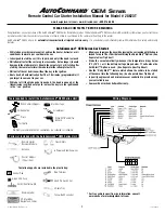
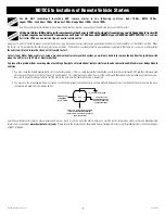
Ignition Key Diagram for Steps 4-7

The vehicle’s wires are found coming off of the key switch.
Remove the panel under the steering column to access
these wires.

4.  Blue Wire (14 AWG) – Ignition 1

Connect the BLUE wire to the ignition 1 wire of your vehicle. This wire will measure
+12 Volts on the test meter in the “run” 

and

     “start” position, and is off in the “lock/

off” and “accessory” positions.

5.  Green (14 AWG) – Ignition 2

Connect the GREEN wire to the Ignition 2 wire in the vehicle.  The Ignition 2 wire can
function in several different ways in your vehicle. It is important to understand how it
works.  The Ignition 2 wire will usually m12 Volts in the “run” position and
is off (ground) in the “lock/off” and “accessory” positions.  In certain vehicles, it may
also show +12 Volts in the “Start” position or Ignition 2 may turn OFF during “Crank”
and turn back ON after the starter disengages.  Carefully note the function of the
Ignition 2 wire.  If the Ignition 2 turns OFF during “Crank”, set Option #4 (section
23). If Ignition 2 stays ON during “Crank”, no options need to be changed.

6.  White Wire (14 AWG) – Accessory

Connect the WHITE wire to the accessory wire which is +12 Volts in the “run” and
“accessory” position, but off in the “start” and “off” positions. In GM vehicles, connect
the white wire to the orange wire that is hot in “run” only.

7.  Yellow (14 AWG) – Starter

Connect the     YELLOW wire to the starter wire.  This wire will m12 Volts on
the test meter in the “start” position only.

Note:  Most Nissan vehicles have two starter wires. Connect both starter wires of the
vehicle to the     YELLOW start wire of the remote starter.

8.  Plug-In On/0ff  Switch

Mount the control switch so that it is easily accessible and so that the “ON” position
is facing upward. Make sure there is enough clearance behind the mounted switch
for the wire connections. Do not let the switch wires touch ground. Do not plug the
switch into the unit until it is mounted first. Connection of this switch is mandatory.
Use a 1/4" drill-bit for the mounting hole.

Plug the ON/OFF control switch into the module just to the right of the power wires.
Turn the switch “on.”

CONTROL HARNESS

ALL WIRES ARE THE SMALLER 18 AWG SIZE

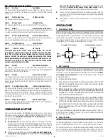
9.  Purple Wire – Hood Pin Switch – Control Harness

The hood pin switch MUST be installed with the remote
starter.  It prevents operation of the remote starter when
the hood is open and is used to initialize the unit. Connect
the PURPLE wire to the hood pin switch using the red
connector.

Note:     If you already have a hood pin switch which is
being used by a car alarm system, you may share the
wiring – but be sure to diode isolate each wire going to
the hood pin switch with the bands of diodes pointing
towards the pin switch as shown at right.

10.  Orange Wire – Brake Shut-off – Control Harness

Connect the ORANGE wire to the brake wire which re12 Volts when the brake
pedal is depressed.  

This wire must be connected

.  It arms a critical safety feature

which disables the remote starter when the brake pedal is depressed.

Note:  In some cars, the ignition must be in the “on” position to test the power in the
brake wire.

WARNING

This car is equipped with a remote control starting device.

Disable before working on car!

AVERTISSEMENT

Ce véhicule est équipé d’un systéme de démarrage a distance.  Mettez-le

hors fonction avant d’eflectuer toute opération d’entretien ou de réparation!

How to share a hood pin

switch with an alarm

To Alarm

To Remote Starter

Summary of Contents for 28623T

Page 1: ...he transmission is shifted out of park unless the key is in the ignition and in the run position Allows you to remove the key while leaving the car running with the doors locked for up to 10 or 15 minutes utilizing the Quick Stop Option See Separate User Tip Sheet Starts the car automatically whenever the temperature drops below 0 F 18 C or if the battery voltage drops below 11 volts when the Cold...

Page 2: ...es Ignition Key Diagram for Steps 4 7 The vehicle s wires are found coming off of the key switch Remove the panel under the steering column to access these wires 4 Blue Wire 14 AWG Ignition 1 Connect the BLUE wire to the ignition 1 wire of your vehicle This wire will measure 12 Volts on the test meter in the run and start position and is off in the lock off and accessory positions 5 Green 14 AWG I...

Page 3: ... installer to open the hood and then press and hold the brake pedal Note The ignition dash lights will come on if the unit is not initialized D While depressing the brake with the engine off and the hood open turn the ignition key to the RUN not start position E Put the car in DRIVE from the PARK position F Put the car back in PARK and release the brake G Turn the key off and remove the key Note C...

Page 4: ... Harness This wire is only used in diesel vehicle applications and is optional This wire can be hooked up to the wait to start light s switched wire behind the dash If Option 9 section 23 is set this wire will feed information to the remote starter as to when to crank the vehicle over This wire is not polarity sensitive REQUIRED FINAL STEPS Note You must have hooked up all required wires and compl...

Page 5: ...e Learning section 12 Option 2 10 Min Run Time 15 Min Run Time This option gives you a choice of run times Option 3 Normal Crank Extended Crank This option will add 50 more crank time to the NoTach starting feature Option 4 Normal IGN 2 not active during Crank This option will turn off the Ignition 2 output thick GREEN wire during cranking It is used to exactly match the remote starter with the ig...

Page 6: ...er Chrysler LHS 99 Transponder Chrysler PT Cruiser 00 Transponder Chrysler Sebring Conv 98 Transponder Daewoo Leganza Transponder Dodge 300 M 99 Transponder Dodge Intrepid 98 Transponder Dodge Neon 00 Transponder Ford Contour 97 Transponder Ford Crown Victoria 98 option Transponder Ford Excursion 01 Transponder Ford Expedition 97 Transponder Ford Explorer 98 Transponder Ford Focus 01 Transponder F...

Page 7: ... when the shifter is in the Park or Neutral position To prevent this problem from occurring when installing a DesignTech International remote starter on the above mentioned GM vehicles or Dodge Dakota vehicles 1 You must leave the Enable Feature option 7 in the factory setting This is a safety feature that requires the user to turn the control switch OFF and then ON again each time they exit the v...

Page 8: ...d of advanced electronic technology DIRECTED is ISO 9001 registered Quality Directed Electronics products are sold and serviced throughout North America and around the world Call 800 876 0800 for more information about our products and services Directed Electronics is committed to delivering world class quality products and services that excite and delight our customers Directed Electronics Inc Vi...

Page 9: ...nafter Unit excluding without limitation any remote transmitters or associated accessories proves defective in materials or workmanship under normal use for the life of the vehicle which the Unit is originally installed During this period so long as the Unit remained installed in the original vehicle Directed will at its option repair or replace this Unit if it is proved defective in workmanship o...

Page 10: ...ransmitter anytime without cancelling out this option Safety Notices 1 When taking your car in for any service or repairs disable the remote starter by switching the Control switch to the OFF position Inform the mechanic 2 Never leave your keys in the Ignition when the vehicle is unattended 3 Do not use this product in a closed garage to avoid excessive carbon monoxide build up Available Accessori...

Page 11: ...ly set that option Try re setting the unit Unplug everything from the module except the black ground wire and LED if you have a plug in LED While pressing the white button on the module connect the power lead The LED on the unit should turn on and stay on Release the white push button and the LED should remain illuminated If not repeat the process being sure to hold in the white button while conne...

Page 12: ...ched if you have been instructed by a technician to do so or you are getting a diagnostic code of 5 flashes Your vehicle may not have a neutral safety switch such as pre 95 GM rear wheel drive vehicles or Dodge Dakotas built prior to 1996 Try this Open the hood and place your foot on the brake Start the vehicle with the key Turn the engine off and release the brake If all of your connections are c...

Page 13: ... change Repeat again to verify if you get the same voltage every time then the module is set up perfectly There is no chart to help you with this it is just trial and error but it will work regardless of the meter you are using Can I use the DesignTech Transmitter with other brands of products NO Due to proprietary technology DesignTech brand products will operate only with DesignTech brand Transm...

Page 14: ... real light bulb can severely damage electrical components in modern vehicles if used improperly Also computer safe LED type test lights with a red and or green LED are NOT airbag safe NEVER test ANY wire within an airbag system harness Always roll down at least one window in the vehicle before beginning work This will prevent you from being accidentally locked out of the vehicle It s okay to have...

Page 15: ...n driver kick panel Cadillac Allante 1993 YELLOW PINK VIO WHT VATS ORANGE LT BLUE WHITE LT GREEN BROWN BLACK in driver kick panel Fleetwood RWD 1990 96 YELLOW PINK N A VATS ORANGE WHITE OR BLUE WHITE LT GREEN BROWN BLACK in driver kick panel may be equipped with VATS Coupe DeVille 1992 93 YELLOW PINK N A N A ORANGE LT BLUE WHITE LT GREEN BROWN BLACK in driver kick panel Eldorado 1992 94 YELLOW PIN...

Page 16: ... N A BLK ORNG WHITE TAN BLK GRAY GREEN ORNG BLACK YELLOW BLK RED Late Model Require resistor value to Disarm Intrepid 1998 02 YELLOW BLUE WHT GRN RED TRANSPONDER BLK ORG WHITE TAN TAN PINK GREEN ORANGE BLACK YELLOW BLK RED 2000 are equipped with Transponder key Intrepid 1996 97 YELLOW BLUE RED WHT N A BLK ORG WHITE TAN RED WHITE BLACK YELLOW BLK RED at fact keyless mod on top of dash Neon 1995 02 ...

Page 17: ...L N A GREEN RED BLK ORANGE 3 2L wire is BLK RED Prelude 1997 02 BLK WHT BLK YEL YELLOW N A WHT BLK GREEN WHITE BLUE N A RED BLACK N A 98 are equipped with transponder key Prelude 1987 96 BLK WHT BLK YEL YELLOW N A WHT BLK GREEN BLUE N A RED BLACK BLUE BLACK Hummer General Hummer 1992 98 Drk Green Lt Green Gray N A Orange Red White Hyundai Accent 2000 02 WHITE GREEN YELLOW N A BLUE PINK BLACK BLUE ...

Page 18: ...EN PURPLE BROWN D BLUE Equipped with Transponder Towncar 1998 02 RED LTBLU WHITE YEL GRAY YEL PINK BLK BLK LT GRN LT GREEN WHITE RED N A BROWN DK BLUE Towncar 1992 97 WHT PINK BRWN PINK PINK BLACK BLK GREEN RED GREEN LT GREEN TAN YELLOW DK GREEN PURPLE BROWN DK BLUE Has a second acc wire Black lt Green Mazda 626 2000 02 GREEN BLACK WHT BLACK RED N A BLUE WHITE GREEN RED RED WHITE GREEN RED Equippe...

Page 19: ...WHITE BLACK RED N A N A WHITE BLUE RED GREEN BLUE BLACK N A RED BLUE GRN WHITE Xterra 2000 04 BLACK YEL BLK WHITE RED YEL N A WHITE BLUE GREEN YEL PINK BLUE L GREEN BLUE RED LGRN BLACK OLDSMOBILE Acheiva 1993 98 YELLOW PINK WHITE N A ORANGE WHITE WHITE N A BROWN BLACK Alero 1999 01 YELLOW PINK DK GREEN N A ORANGE WHITE VIOLET WHT N A BROWN BLACK Equipped with passlock II Arora 2001 02 PURPLE PINK ...

Page 20: ...REEN GREEN RED Echo 2000 01 BLACK BLACK RED BLACK YEL N A WHITE BLUE GREEN WHITE GREEN RED BLUE YELLOW GREEN WHITE RED NEED RELAY FOR STARTER INTERUPT Land Cruiser 1999 02 BLK WHT BLUE BLK BLK RED N A BLACK GREEN WHITE BLACK N A GREEN GREEN ORG Land Cruiser 1991 97 BLK WHT Blk Red or Blk GRN BLACK YEL N A BLUE RED GREEN WHITE BLACK N A GREEN GREEN RED Land Cruiser 1998 BLK WHT BLK BLUE BLK RED N A...

Reviews: