Page 3
579-1034AC Rev G
TrueAlert ES Addressable Indoor A/O Notification Appliances Installation Instructions
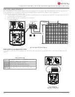
Setting the address DIP Switch
Each addressable TrueAlert ES notification appliance has a unique address that is set using an eight position DIP switch (ADDR1). Assign up to 127
unique addresses to an SLC, however, the total appliance loading available may be less due to appliance current requirements.
To set the address, complete the following steps:
1.
Insert a number 1 or number 2 Phillips screwdriver, or a similar sized object, into the opening at the bottom of the appliance and unclip the
appliance from the backplate. See Figure 3.
2.
Set the switches using a non-metallic stylus, or the equivalent.
3.
Record the set address.
To access the switches:
ADDR1
The DIP switch shown is
set at address 7
Not used
001
101
011
111
64
65
66
67
68
69
70
71
72
73
74
75
76
77
78
79
80
81
82
83
84
85
86
87
88
89
90
91
92
93
94
95
96
97
98
99
100
101
102
103
104
105
106
107
108
109
110
111
112
113
114
115
116
117
118
119
120
121
122
123
124
125
126
127
DIP SWITCHES 5 THROUGH
7
000
100
010
110
Fig 3: Setting the DIP Switch Address
Setting the horn configuration switch
Certain options for the horn can be configured directly on the appliance using the Configuration switch (CFIG1) on the back of the appliance. See
Table 3: AO Settings
Position 1
Configuration Control: OFF to enable Local Audible control
(positions 2-7 below), ON for Panel control.
Position 2
Audible Volume: High (OFF), Low (ON).
Position 3
CAN Horn mode: switch must be set to OFF.
Position 4
Legacy NAC mode: switch must be set to OFF.
Position
5, 6, 7, 8
These switches are unused by the horn. Leave them set to
OFF.
To access the switches:
CFIG1
Device
configuration switch
Not used (Leave at OFF)
Fig 4: Setting the
Appliance Configuration


