background image


95 

15 

  Quick Link   

The  Quick  Link  application  provides  you  with  convenient  access  to  Autel

’s  official 

website  and  many  other  well-known  sites  in  automotive  service,  which  offers  you 
abundant information and resources, such as technical help, knowledge base, forums, 
training, and expertise consultations, etc. 
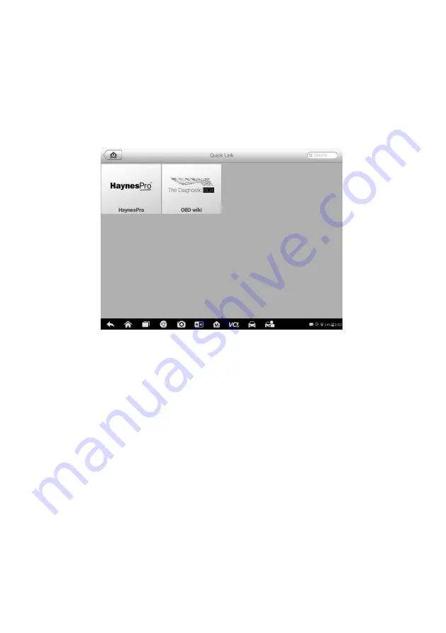
 

Figure 15-1 

Sample Quick Link Screen 


To open a quick link


1.  Tap 

Quick Link

 on the MaxiSys Job Menu. The Quick Link application screen 

displays. 

2.  Select a website thumbnail from the main section. The Chrome browser is 

launched and the selected website is opened. 

3.  Now you can start exploring the website!

Summary of Contents for MaxiSys MS908S

Page 1: ...on the latest information available at the time of printing Autel reserves the right to make changes at any time without notice While information of this manual has been carefully checked for accuracy no guarantee is given for the completeness and correctness of the contents including but not limited to the product specifications functions and illustrations Autel will not be liable for any direct ...

Page 2: ...ted Before using the device always refer to and follow the safety messages and applicable test procedures provided by the manufacturer of the vehicle or equipment being tested Use the device only as described in this manual Read understand and follow all safety messages and instructions in this manual Safety Messages Safety messages are provided to help prevent personal injury and equipment damage...

Page 3: ...he ignition coil distributor cap ignition wires and spark plugs These components create hazardous voltages when the engine is running Keep a fire extinguisher suitable for gasoline chemical and electrical fires nearby Do not connect or disconnect any test equipment while the ignition is on or the engine is running Keep the test equipment dry clean free from oil water or grease Use a mild detergent...

Page 4: ...EHICLE IDENTIFICATION 24 NAVIGATION 27 MAIN MENU 30 DIAGNOSIS 31 PROGRAMMING AND CODING 43 GENERIC OBD II OPERATIONS 46 EXITING DIAGNOSTICS 50 5 SERVICE 51 OIL RESET SERVICE 51 ELECTRIC PARKING BRAKE EPB SERVICE 52 TIRE PRESSURE MONITORING SYSTEM TPMS SERVICE 52 BATTERY MANAGEMENT SYSTEM BMS SERVICE 53 STEERING ANGLE SENSOR SAS SERVICE 53 DIESEL PARTICLE FILTER DPF SERVICE 54 IMMOBILIZER IMMO SERV...

Page 5: ...MPLAINT 88 DATA LOGGING 90 COMMUNITIES 91 TRAINING CHANNELS 92 FAQ DATABASE 93 14 ACADEMY 94 15 QUICK LINK 95 16 MAXISCOPE 96 SAFETY INFORMATION 96 GLOSSARY 98 MAXISCOPE MODULE 100 SCREEN LAYOUT AND OPERATIONS 103 TROUBLESHOOTING 109 MAXISCOPE FIRMWARE UPDATE 110 17 DIGITAL INSPECTION 111 ADDITIONAL ACCESSORIES 112 OPERATIONS 115 18 MAINTENANCE AND SERVICE 117 MAINTENANCE INSTRUCTIONS 117 TROUBLES...

Page 6: ...vi SERVICE PROCEDURES 119 19 COMPLIANCE INFORMATION 122 20 WARRANTY 124 12 MONTH LIMITED WARRANTY 124 ...

Page 7: ...ch as buttons and menu options Example Tap OK Notes and Important Messages Notes A NOTE provides helpful information such as additional explanations tips and comments Example NOTE New batteries reach full capacity after approximately 3 to 5 charging and discharging cycles Important IMPORTANT indicates a situation which if not avoided may result in damage to the tablet or vehicle Example IMPORTANT ...

Page 8: ...ons Illustrations used in this manual are samples and the actual testing screen may vary for each vehicle being tested Observe the menu titles and on screen instructions to make correct option selection Procedures An arrow icon indicates a procedure Example To use the camera 1 Tap the Camera button The camera screen opens 2 Focus the image to be captured in the view finder 3 Tap the blue circle Th...

Page 9: ...gnose symptoms codes and customer complaints easily quickly and efficiently There are two main components to the MaxiSys system MaxiSys Display Tablet the central processor and monitor for the system Vehicle Communication Interface VCI the device for accessing vehicle data NOTE Autel provides two optional VCI devices for your choice One is the Wireless Diagnostic Interface the other is the J2534 P...

Page 10: ...ible Stand extends from the back to allow hands free viewing of the tablet at a 30 degree angle 3 Camera Lens 4 Camera Flash Figure 2 3 MaxiSys Tablet Left Side 1 Mini SD Secure Digital Card Slot 2 Mini USB Universal Serial Bus Port it cannot be used at the same time with the No 4 USB Port in Figure 2 4 MaxiSys Tablet Top View 3 Head Phone Jack Labelling Place ...

Page 11: ...nt temperature between 0 C and 45 C If charge the battery when the temperature is out of range the battery may catch on fire Internal Battery Pack The tablet can be powered with the internal rechargeable battery which if fully charged can provide sufficient power for about 7 5 hours of continuous operation AC DC Power Supply The tablet can be powered from a wall socket using the AC DC power adapte...

Page 12: ...d Support up to 32GB HDMI Camera rear 8 0 Megapixel AF with Flashlight Sensors Gravity Accelerometer Ambient Light Sensor ALS Audio Input Output Microphone Dual Speakers 4 Band 3 5 mm stereo standard headset jack Power and Battery 11000 mAh 3 7 V lithium polymer battery Charging via 12 V AC DC power supply with the temperature between 0 C and 45 C Input Voltage 12 V 9 24 V Power Consumption 6 5 W ...

Page 13: ...Vehicle LED blinks green when the device is communicating with the vehicle s network 4 Error LED lights solid red when serious hardware failure occurs also blinks red when the device is updating software firmware 5 BT LED lights solid green when the device is connected with the tablet through BT communication 6 USB LED lights solid green when the device is properly connected and communicating with...

Page 14: ...rent 200 mA 12 VDC Operating Temp 0 C to 50 C ambient Storage Temp 20 C to 70 C ambient Dimensions LxWxH 147 5 mm 5 80 x 85 5 mm 3 37 x 29 0 mm 1 14 Weight 215 g 0 473 lb Power Sources The Wireless Diagnostic Interface operates on 12 volt vehicle power which it receives through the vehicle data connection port The unit powers on whenever it is connected to an OBD II EOBD compliant data link connec...

Page 15: ...ower up when the device is self testing 6 USB Port J2534 Programming Capability The J2534 ECU Programming Device is a SAE J2534 1 2 compliant PassThru programming interface device Using the updated OEM software it is capable of replacing the existing software firmware in the Electronic Control Units ECU programming new ECUs and fixing software controlled drivability issues and emission issues Comm...

Page 16: ...er Technical Specifications Table 2 3 J2534 ECU Programming Device Specifications Item Description Communications Wireless BT V2 1 EDR USB 2 0 Wireless Frequency Wireless BT V2 1 EDR 2 4GHz Input Voltage Range 12 VDC to 24 VDC Supply Current 170 mA 12 VDC 100 mA 24 VDC Operating Temp 0 C to 60 C ambient Storage Temp 65 C to 100 C ambient Dimensions L x W x H 149 mm 5 87 x 86 mm 3 38 x 35 mm 1 28 W...

Page 17: ...es The adapter used depends on the type of vehicle being tested The most common adapters are shown below Adapters PSA 2 and Fiat 3 are available for MaxiSys MS908S Pro only Benz 14 EU Only Chrysler 16 America Only BMW 20 Kia 20 Nissan 14 GM Daewoo 12 Honda 3 Fiat 3 PSA 2 Benz 38 VW Audi 2 2 Mitsubishi Hyund ai 12 16 Other Accessories Standard 2 0 USB Cable Connects the tablet to the VCI unit ...

Page 18: ... only Cigarette Lighter Provides power to the tablet or the J2534 programming device through connection to the vehicle s cigarette lighter receptacle as some non OBD II vehicles cannot provide power via the DLC connection Clipper Cable Provides power to the tablet or the J2534 programming device through connection to the vehicle s battery for MaxiSys MS908S Pro only Lighter Fuse x2 A safety device...

Page 19: ...ob Menu is shown Figure 3 1 Sample MaxiSys Job Menu 1 Application Buttons 2 Locator and Navigation Buttons 3 Status Icons NOTE The screen is locked by default upon startup It is recommended to lock the screen when not in use to protect information in the system and conserve the power Almost all operations on the tablet are controlled through the touch screen The touch screen navigation is menu dri...

Page 20: ...ystem for saved data files See Data Manager on page 71 Settings Accesses the system settings menu and general tablet menu See Settings on page 75 Update Accesses system software update menu See Update on page 80 VCI Manager Accesses VCI connection menu See VCI Manager on page 82 Support Launches the Support platform that synchronizes Autel s on line service base station with the MaxiSys tablet See...

Page 21: ...ons Name Button Description Locator Indicates the location of the screen Swipe the screen left or right to view the previous or next screen Back Returns to the previous screen Android Home Returns to Android System s Home screen Recent Apps Displays a list of applications that are currently working Tap an app icon to launch To remove an app swipe it to the right Browser Launches the Chrome Interne...

Page 22: ...stored image 5 Tap the Back or Home button to exit the camera application Refer to Android documentation for additional information System Status Icons These are the standard status icons of the Android operating system Your MaxiSys display tablet is a fully functional Android Pad Refer to Android documentation for additional information Power Down All vehicle communications must be terminated bef...

Page 23: ...17 Reboot System In case of system crash long press the Lock Power button and tap Reboot to restart the system ...

Page 24: ...on at the bottom bar on the screen if a green check displays at the lower right corner the MaxiSys MS908S MaxiSys MS908S Pro Diagnostic Platform is ready to start vehicle diagnosis Vehicle Connection The method used to connect the VCI device to a vehicle s DLC depends on the vehicle s configuration as follows A vehicle equipped with an On board Diagnostics Two OBD II management system supplies bot...

Page 25: ...connection to the vehicle battery To connect to a Non OBD II Vehicle 1 Connect the main cable s female adapter to the Vehicle Data Connector on the VCI device and tighten the captive screws 2 Locate the required OBD I adapter and connect its 16 pin jack to the main cable s male adapter 3 Connect the attached OBD I adapter to the vehicle s DLC NOTE Some adapters may have more than one adapter or ma...

Page 26: ...vice which comes with the MaxiSys MS908S Pro tool kit supports 2 communication methods with the tablet BT and USB Pairing Up via BT Among all methods BT pairing is recommended as the first choice for the communication between the tablet and the VCI device The working range for BT communication is about 210 feet 70 m this means you can perform vehicle diagnosis freely around the workshop with great...

Page 27: ...CI device and is ready to perform vehicle diagnosis Refer to BT Pairing on page 83 for additional information USB Cable Connection The USB cable connection is a simple and quick way to establish communication between the tablet and the VCI device After properly connecting the USB cable from the tablet to the VCI device the VCI navigation button at the bottom bar of the screen shows a green tick ic...

Page 28: ...problem with the device in this case contact for technical support B If the VCI device is unable to establish a communication link a prompt message displays with check instructions The following conditions are the possible causes for this massage to display The VCI device is unable to establish a communication link with the vehicle You ve selected a system for testing that the vehicle is not equip...

Page 29: ...o the MaxiSys Job Menu VIN Scan Touching this button opens a dropdown list tap Auto Detect for auto VIN detection tap Manual Input to enter VIN manually All Displays all the vehicle makes in the vehicle menu History Displays the stored test vehicle history records This option provides you direct access to the previously tested vehicle recorded during previous test sessions See Vehicle History on p...

Page 30: ...formation such as vehicle coverage and function list etc for the corresponding vehicle make Vehicle Identification The Maxisys diagnostic system supports four methods for Vehicle Identification 1 Auto VIN Scan 2 Manual VIN Input 3 Manual Vehicle Selection 4 OBD Direct Entry Auto VIN Scan The MaxiSys diagnostic system features the latest VIN based Auto VIN Scan function to identify CAN vehicles in ...

Page 31: ... for vehicle VIN scan Figure 4 4 Sample Vehicle Selection Screen Select Automatic Selection and the system will proceed to acquire VIN information automatically or allow users to input the VIN manually Manual VIN Input For some vehicles that do not support the Auto VIN Scan function the MaxiSys diagnostic system allows you to enter the vehicle VIN manually or simply take a photo of the VIN sticker...

Page 32: ...elect the vehicle manually Step by step Vehicle Selection This mode of vehicle selection is menu driven you simply follow the screen prompts and make a series of choices Each selection you make advances you to the next screen A Back button at the lower right corner of the screen returns you to the previous screen Exact procedures may vary somewhat by various vehicles being serviced Alternative Veh...

Page 33: ...ics Toolbar The Diagnostics Toolbar contains a number of buttons that allow you to print or save the displayed data and make other controls The table below provides a brief description for the operations of the Diagnostics toolbar buttons Table 4 2 Diagnostics Toolbar Buttons Name Button Description Home Returns to the MaxiSys Job Menu Vehicle Swap Exits the diagnostic session and returns to the v...

Page 34: ...an be reported and sent to the technical center via the internet Go to the Support application to follow up the processing progress see Data Logging on page 90 Send Taps it to submit the Data Logging report to the technical center via the internet To print data in Diagnostics 1 Tap the Diagnostics application button from the MaxiSys Job Menu The Print button on the diagnostic toolbar is available ...

Page 35: ...status of the vehicle Main Section The Main Section of the screen varies depending on the stage of operations The Main Section can show vehicle identification selections the main menu test data messages instructions and other diagnostic information Functional Buttons The displayed Functional Buttons at this section of the screen varies depending on the stage of operations They can be used to navig...

Page 36: ...ou to establish a data link to the electronic control system of the test vehicle via the VCI device for vehicle diagnosis service or programming You can operate functional tests retrieve vehicle diagnostic information such as trouble codes event codes and live data and perform ECU reprogramming for various vehicle control systems such as engine transmission ABS and more The Vehicle Diagnostics scr...

Page 37: ...l the systems on the vehicle s ECU in order to locate fault systems and retrieve DTCs The sample operation interface of Auto Scan displays as below Figure 4 7 Sample Auto Scan Operation Screen 1 Navigation Bar 2 Main Section 3 Functional Buttons Navigation Bar 1 List Tab displays the scanned data in list format 2 Tree Tab display the scanned data in system distribution diagram format 3 Progress Ba...

Page 38: ...ult is shown in blue font whereas the scanned system that has been detected with fault present is shown in red font Tab the button to the right of the system item on which you want to perform further diagnosis and other test activities A Function Menu screen Figure 4 8 shall then display Functional Buttons The table below provides a brief description of the Functional Buttons operations in Auto Sc...

Page 39: ...ormation provides the retrieved ECU information in detail Selecting opens an information screen Read Codes displays detailed information of DTC records retrieved from the vehicle control module Erase Codes erases DTC records and other data from the ECM Live Data retrieves and displays live data and parameters from the vehicle s ECU Active Test provides specific subsystem and component tests This s...

Page 40: ...e Diagnosis section 4 Locate the required system for testing by Auto Scan or through menu driven selections in Control Units 5 Select the desired test from the Function Menu ECU Information This function retrieves and displays the specific information for the tested control unit including unit type version numbers and other specifications The sample ECU Information screen displays as below Figure ...

Page 41: ... status of the retrieved codes Description Column detailed descriptions for the retrieved codes Snowflake Icon only displays when freeze frame data is available for viewing Selecting displays a data screen which looks very similar to the Read Codes interface therefore same operation method may be applied 3 Functional Button in this case only a Back or sometimes an ESC button is available tap it to...

Page 42: ...y from one vehicle to another The parameters display in the order that they are transmitted by the ECM so expect variation between vehicles Gesture scrolling allows you to quickly move through the data list Simply touch the screen and drag your finger up or down to reposition the parameters being displayed if the data covers more than one screen The figure below shows a typical Live Data screen Fi...

Page 43: ...ently Analog Gauge Mode displays the parameters in form of an analog meter graph Text Mode the default mode that displays the parameters in texts and shows in list format NOTE Reading of status parameters such as a switch reading which are mostly in word form like ON OFF ACTIVE and ABORT etc can only be displayed in Text Mode Whereas reading of value parameters such as a sensor reading can be disp...

Page 44: ...data the recorded data is then stored as a video clip in the Data Manager application for future reviews This function could be triggered automatically at preset threshold value or manually as you choose and the triggering mode and record duration can be configured in the Setting mode of Live Data Freeze displays the retrieved data in freeze mode Previous Frame moves to the previous frame in the f...

Page 45: ...hold values for data recording and make other controls Figure 4 12 Sample Setting Mode in Live Data There are four navigation buttons on top of the Setting mode screen Range displays the configuration screen on which you can set the threshold values an upper limit and a lower limit for triggering the buzzer alarm This function is only applied to the Waveform Graph display mode a MIN taps it to ope...

Page 46: ...rd Setting on which you can set the trigger type duration and trigger point for the data recording function a Trigger Type sets the trigger mode for data recording mainly of two kinds Manual and Auto There are four options available 1 Manual allows you to manually start and stop data recording 2 DTC auto triggers data recording when any DTC is detected 3 DTC Check Mode auto triggers data recording...

Page 47: ...available tests display in the menu During an active test the tester outputs commands to the ECU in order to drive the actuators This test determines the integrity of the system or parts by reading the engine ECU data or by monitoring the operation of the actuators such as switching a solenoid relay or switch between two operating states Selecting Active Test opens a menu of test options that vari...

Page 48: ...ation screen displays a list of operational and vehicle status information which mainly consists of four parts 1 The first part in the top line shows the description of the operation being performed and the execution status is displayed on the right such as Completed or Activated etc 2 The second part shows the preconditions or requirements for executing the operation being selected 3 The third pa...

Page 49: ...uter software on the vehicle to the latest version as well as to reprogram adaptive data for certain components after making repairs or replacements NOTE The programming function can only be applied through connection with the J2534 programming device which serves as a PassThru interface to establish communication with and transfer data to the vehicle s ECU Available programming or coding operatio...

Page 50: ...ant Coding screen displays a list of vehicle components and the coding information which mainly consists of three parts 1 The top line on the list displays the instruction of how to use the functional button at the lower right corner of the screen to manipulate the coding operations 2 The second part under the top line of the list displays all available systems for coding on the left side and the ...

Page 51: ...ormation and follow the instruction to execute the programming procedure Re flash Errors IMPORATANT When reprogramming onboard always make sure the vehicle battery is fully charged and in good working condition During reprogramming there is a risk of having the operation failure if voltage falls below the proper operation voltage Sometimes a failed operation can be recovered but there is a chance ...

Page 52: ...stics database Functions of the diagnostics toolbar buttons at the top the screen are the same as those available for specific vehicle diagnostics See Table 4 2 Diagnostics Toolbar Buttons on page 27 for details General Procedure To access the OBD II EOBD diagnostics functions 1 Tap the Diagnostics application button from the MaxiSys Job Menu The Vehicle Menu displays 2 Tap the EOBD button There a...

Page 53: ...ard Monitor Component Test Vehicle Information Vehicle Status NOTE Some functions are supported only on certain vehicle makes Function Descriptions This section describes the various functions of each diagnostic option DTC FFD When this function is selected the screen displays a list of Stored Codes and Pending Codes When the Freeze Frame data of certain DTCs are available for viewing a snowflake ...

Page 54: ...to assist the service technician after a vehicle repair and after clearing diagnostic information by reporting test results after a single driving cycle a If a test failed during the driving cycle the DTC associated with that test is reported If the pending fault does not occur again within 40 to 80 warm up cycles the fault is automatically cleared from memory b Test results reported by this servi...

Page 55: ...ce the last time the DTCs are erased This Driving Cycle displays the status of monitors since the beginning of the current drive cycle Live Data This function displays the real time PID data from ECU Displayed data includes analog inputs and outputs digital inputs and outputs and system status information broadcast on the vehicle data stream Live data can be displayed in various modes see Live Dat...

Page 56: ...ns with the vehicle before closing the Diagnostics application NOTE Damage to the vehicle electronic control module ECM may occur if communication is disrupted Make sure the all connections such as data cable USB cable and wireless or wired network are properly connected at all times during testing Exit all tests before disconnecting the test cable or powering down the tool To exit the Diagnostics...

Page 57: ...wo application choices Diagnosis and Hot Functions The Diagnosis enables the reading and clearing of codes which is sometimes necessary after completing certain special functions Hot Functions consists of sub functions of the selected special function Figure 5 1 Sample Service Menu Several most commonly used services are described in this chapter Oil Reset Service Perform reset for the Engine Oil ...

Page 58: ... and setting brakes after disc or pad replacement EPB Safety It can be dangerous to perform Electric Parking Brake EPB system maintenance so before you begin the service work please keep these rules in mind Ensure that you are fully familiar with the braking system and its operation before commencing any work The EPB control system may be required to be deactivated before carrying out any maintena...

Page 59: ...a battery with a different capacity mAh the vehicle may require reprogramming of the new battery type in addition to performing the battery reset Consult the vehicle manual for additional vehicle specific information Steering Angle Sensor SAS Service Steering Angle Sensor Calibration permanently stores the current steering wheel position as the straight ahead position in the steering angle sensor ...

Page 60: ...ed high exhaust temperature must be obtained In the event of the car being driven in such a way that regeneration is not possible i e frequent short journeys a diagnostic trouble code will eventually be registered in addition to the DPF light and Check Engine indicators displaying A service regeneration can be requested in the workshop using the diagnostic tool Before performing a forced DPF regen...

Page 61: ...urance companies offer lower rates for vehicles that are equipped with an immobilizer As an anti theft device an immobilizer disables one of the systems needed to start a car s engine usually the fuel supply or the ignition This is accomplished by radio frequency identification between a transponder in the ignition key and a device called a radio frequency reader in the steering column When the ke...

Page 62: ...ing the reported solution cases and the advisory reports of the MaxiSys users from all over the world Information in the MaxiFix database is organized into a series of diagnostic tips that are designed to quickly lead you to the root cause of a particular problem on the test vehicle which will help you quickly find solutions for various diagnostic problems Navigation You need to register the devic...

Page 63: ...lect Vehicle button on the Header allows you to specify the vehicle which you want to reference on MaxiFix by selecting each of the vehicle attribute from a sequence of option lists This feature helps to filter out the searches that allow only the information that applies to the identified vehicle to display NOTE All attributes must be specified to make a complete vehicle selection for the most ef...

Page 64: ... from the list After completing the vehicle selection procedure the identified vehicle is shown on the Header 2 Enter a Search Term MaxiFix has an exclusive one stop lookup that helps you find all of MaxiFix resources by one click Simply enter a search term into the search bar on the Header to begin the search 3 Proven Results The powerful MaxiFix database gives you proven results The typical Maxi...

Page 65: ...ps and Real Fixes and displays search results Ask allows you to ask a question in the community My MaxiFix shows all your posts including Questions and Fixes in the community and allows you to view your personal profile select your vehicle preference and share your tips My Messages shows a list of message notifications which is relevant to your activities in the Question section Support opens the ...

Page 66: ...cular vehicle repair issue in the community To ask a MaxiFix Question 1 If not already done click Select Vehicle on the Header to specify the vehicle you are asking about 2 Click Ask on the Navigation Menu at the bottom of the screen to open the Ask page 3 On the Ask page find Ask for Help fill in the following sections to ask a question The Ask page has four sections Subject this is where you ent...

Page 67: ... list allows you to limit the choices that displayed on the Select Vehicle list to specific years and makes Click Set Year or Set Make to set your preferred models The preferred makes will also be displayed in the Filter options on the Home page Share a Tip allows you to share your personal repair experience with the community Click My MaxiFix on the Navigation Menu at the bottom of the screen to ...

Page 68: ... appear on the top right corner of My Messages if there is any new or unread message in the Question section The number on the notification icon indicates the total number of the new and unread messages The displayed number will be reduced correspondingly after viewing The message notification will appear under the following two conditions 1 Your question or answer is replied by other MaxiFix comm...

Page 69: ...wer 2 A score of 3 is awarded when you close a question 3 A score of 2 is awarded if your closed question is marked as Adopted by no less than 20 community members 4 A score of 1 is awarded if your answer is selected as the Adopted Answer for a closed question which is marked as Adopted by no less than 20 community members 5 A score of 1 is awarded to each of the first three respondents Support Su...

Page 70: ...ck Returns to the previous screen Diagnostics Directs to Diagnostics screen to activate a direct test session Enter Edit Taps it to show the editing toolbar to print or delete the selected file Delete Taps it to delete the selected vehicle record item from the list Search Quickly locates the vehicle record by entering the vehicle name or test path Cancel Taps it to cancel edit or file search Edit ...

Page 71: ...ehicle History Screen 1 Top Toolbar Buttons navigates and makes various controls of the application 2 Main Section displays all the vehicle history records information To activate a test session for the recorded vehicle 1 Tap Shop Manager on the MaxiSys Job Menu 2 Select Vehicle History 3 Tap Diagnostics at the bottom of the thumbnail of a vehicle record item Or 4 Select a vehicle record item by t...

Page 72: ...vehicle history record thumbnail from the main section The Historical Test record sheet displays 4 Tap Edit to start editing 5 Tap on each item to input information or add attaching files or images NOTE The vehicle VIN number or license and the customer information account are correlated by default Adding one of the information will automatically associate the other item in the record sheet provid...

Page 73: ...on the top toolbar 4 Tap on each field to input the appropriate information 5 Tap Done to save the updated workshop information sheet or tap Cancel to exit without saving Customer Manager The Customer Manager function allows you to create and edit customer accounts It helps you to save and organize all customer information accounts that are correlated with the associated test vehicle history recor...

Page 74: ...editing 5 Tap on the input field where needs to be altered or supplemented and enter updated information 6 Tap Done to save the updated information or tap Cancel to exit without saving To delete a customer account 1 Tap Shop Manager on the MaxiSys Job Menu 2 Select Customer Manager 3 Select a customer account by tapping the corresponding name card A Customer Information sheet displays 4 Tap Edit o...

Page 75: ...ory Notes Screen 1 Functional Buttons navigates and make various controls of the function 2 Main Section displays the note list on the left column and the detail information of the selected note on the right column Table 7 2 Function Buttons in History Notes Name Button Description Back Returns to the previous screen Delete Taps it to delete the selected note Search Quickly locates the required no...

Page 76: ...tory Notes Take a Photo Takes photos and adds the files to History Notes Save Saves notes To add a note in History Notes 1 Access History Notes 2 Tap Add Notes An edit window displays 3 Tap on the Title bar to input a note title 4 Tap on the blank space below to edit a text note or remark 5 Select a function button on the top to add files in any form you choose 6 Tap Save to save the note tap Disc...

Page 77: ...file system menu Different file types are sorted separately under different options there are six types of information files to be viewed or played back Figure 8 1 Sample Data Manager Main Screen Operations Data Manager Operations are based on toolbar controls details are explained in the following sections Image Files The Image section is a JPG database containing all captured screenshot images ...

Page 78: ...formation Cancel Taps it to close the editing toolbar or cancels file search Search Quickly locates the image file by entering the vehicle name test path file name or file info Info Taps it to open a window displaying the detail information of the image Print Taps it to print the selected image Delete Taps it to delete the selected image To edit image information 1 Select Data Manager from the Max...

Page 79: ...ges the selected thumbnail displays a tick icon at the bottom right corner 5 Tap the Delete button and then Delete Selected now the selected images are deleted PDF Files The PDF section stores and displays all PDF files of saved data After entering the PDF database select a PDF file to view the stored information This section uses the standard Adobe Reader application for file viewing and editing ...

Page 80: ...he MaxiSys Diagnostics System Selecting this section opens a managing screen on which you can check all the available vehicle diagnostic applications Select the vehicle firmware you want to delete by tapping on the car brand icon the selected item will display a blue tick at the upper right corner Tap the Delete button on the top bar to delete the firmware from the system database Data Logging The...

Page 81: ...option allows you to adjust the measurement unit for the diagnostic system To adjust the unit setting 1 Tap the Settings application on the MaxiSys Job Menu 2 Tap the Unit option on the left column 3 Select the required measurement unit Metric or English A tick icon will display to the right of the selected unit 4 Tap the Home button on the top left corner to return to the MaxiSys Job Menu Or sele...

Page 82: ...ft corner to return to the MaxiSys Job Menu Or select another setting option for the system setup Printing Operations To install the MaxiSys Printer driver program 1 Download Maxi PC Suite from www autel com Supports Updates Firmware Downloads Update Client and install to a Windows based PC 2 Double click on Setup exe item 3 Select the installation language and the wizard will load momentarily 4 F...

Page 83: ...ows you to enable or disable the wired network connectivity as well as to perform Ethernet configuration To operate Ethernet configuration 1 Tap Settings on the MaxiSys Job Menu 2 Tap Wired Network on the left column 3 Tap ON OFF to enable the Wired Network connection If the connectivity is enabled the button turns blue or if disabled the button turns gray 4 Tap the button to the right of the Ethe...

Page 84: ...ived by the MaxiSys device a notification message displays on the MaxiSys Job Menu Press on the message bar and drag it down and the received messages are shown in the list slide the list up or down to view all if the message list covers more than one screen Tap a specific message to launch the corresponding application For example if you tap on an Update notification message the Update applicatio...

Page 85: ...em settings for the Android system platform regarding wireless and networks settings various device settings such as sound and display as well as system security settings and check the associated information about the Android system etc Refer to Android documentation for additional information About The About option provides information of the MaxiSys diagnostic device regarding the product name v...

Page 86: ...nstalling an update to the MaxiSys Diagnostic System firmware A notification message displays if an update is available when the Notifications function is enabled in the Settings application See Notification Center on page 78 Figure 10 1 Sample Update Screen 1 Navigation and Controls Home Button returns to the MaxiSys Job Menu Update All updates all available updates Search Bar searches specific u...

Page 87: ...re 1 Power up the tablet and ensure that it is connected to a power source and with steady internet connection 2 Tap the Update application button from the MaxiSys Job Menu or tap the update notification message when received one The Update application screen displays 3 Check all available updates If you decide to update all the items tap the Update All button If you only want to update some indiv...

Page 88: ... as Paired otherwise it displays as Unpaired Update for VCI software only update VCI software via internet through the MaxiSys tablet networking using USB connection Select a connection mode to manage and set up connection 2 Settings this section allows you to manage wireless pairing or set up network connection BT Setting searches and displays the type and a partial serial number for all of the d...

Page 89: ...e may display as Maxi suffixed with a serial number Select the required device for pairing 8 When paring is successfully done the connection status displayed to the right of the device name is shown as Paired 9 Wait a few seconds and the VCI button on the system Navigation bar at the bottom of the screen shall display a green tick icon indicating the tablet is connected to the VCI device 10 Tap th...

Page 90: ...at run TeamViewer are identified by a globally unique ID The first time the Remote Desk application is started this ID is generated automatically based on the hardware characteristics and will not change later on Make sure the tablet is connected to the Internet before launching the Remote Desk application so that the tablet is accessible to receive remote support from the third party Figure 12 1 ...

Page 91: ...ke control of the tablet remotely 4 Provide your ID to the partner and wait for him her to send you a remote control request 5 A popup displays to ask for your confirmation to allow remote control on your device 6 Tap Allow to accept or tap Deny to reject Refer to the associated TeamViewer documents for additional information ...

Page 92: ...e 1 Visit the website http pro autel com 2 If you already have and Autel account Sing In with your account ID and password 3 If you are a new member to Autel click on the Create Autel ID button on the left side to create an ID 4 Enter the required information in the input fields and click Get Verification Code button to get the verification code for email validation 5 The online system will automa...

Page 93: ...The narrow column on the left is the main menu selecting one subject from the main menu displays the corresponding functional interface on the right My Account The My Account screen displays the comprehensive information of the user and the product which is synchronized with the on line registered account including User Info Device Info Update Info and Service Info Personal Info The User Info and ...

Page 94: ...ion such as the fault type changed components or system reinstallation etc will be recorded and updated to the associated online product account which will be synchronized to the Service Info section User Complaint The User Complaint screen allows you to establish a new complaint case as well as to view historical complaint records Screen Layout Figure 13 2 Sample Complaint Screen The User Complai...

Page 95: ...aint on the Main Menu 4 Tap New Complaint at the upper right corner A selection menu with a category of service channels displays 5 Select your target service channel and click Next to continue A standard complaint form displays on which you are allowed to enter detailed information such as personal information vehicle information and device information you can also attach image or PDF files with ...

Page 96: ...ent saved data loggings on the diagnostic system The support personnel receive and process the submitted reports through the Support platform and send back problem solutions within 48 hours to the corresponding Data Logging session on which you are also allowed to have a direct conversation with the support personnel Figure 13 3 Sample Data Logging Screen To make a reply in a Data Logging session ...

Page 97: ...to ask a question about the MaxiSys tablet tap MaxiSys to start a discussion 3 Enter your topic and the discussion content in the appropriate input field 4 Select a category or edit tags for the discussed post This will help other members with similar interest to find your post 5 Tap OK to submit the post To join and reply to a discussion post 1 Select a forum group that you are interested in whet...

Page 98: ...User Profile Profile displays the user s personal information and member status The Related links allow you to check the Top Users ranked according to their points and levels in the communities as well as to find out other online users Avatar allows you to select an image to set as your personal Avatar to be displayed in the communities Stuff displays all the discussions you ve posted at various f...

Page 99: ...s frequently asked and answered about the use of Autel s online member account and shopping and payment procedures Account displays questions and answers about the use of Autel s online user account Shopping Payment displays questions and answers about online product purchase and payment methods or procedures ...

Page 100: ... articles and technical bulletins produced by top notch technicians and product experts Please view the materials that are saved on the tablet or view technical articled from our online forum by clicking the links displayed under this application ...

Page 101: ... and resources such as technical help knowledge base forums training and expertise consultations etc Figure 15 1 Sample Quick Link Screen To open a quick link 1 Tap Quick Link on the MaxiSys Job Menu The Quick Link application screen displays 2 Select a website thumbnail from the main section The Chrome browser is launched and the selected website is opened 3 Now you can start exploring the websit...

Page 102: ...t electric shock take all necessary safety precautions when working on equipment where voltages above the specified input range may be present Contact with voltages outside of the specified measuring range presents a risk of electric shock To prevent injury or death the oscilloscope must not be directly connected to the mains line power To measure mains voltages use a differential isolating probe ...

Page 103: ...cifications for both the storage and usage of the oscilloscope see Safety Information on page 96 E Product Maintenance The product contains no user serviceable parts Repair servicing and calibration require specialized test equipment and must only be performed by Autel Tech Support or an approved service provider DANGER To prevent injury or death do not use the product if it appears to be damaged ...

Page 104: ...yed sine wave has half the power of the input sine wave about 71 of the amplitude Block Mode A sampling mode in which the computer prompts the oscilloscope to collect a block of data into its internal memory before stopping the oscilloscope and transferring the whole block into computer memory This mode of operation is effective when the input signal being sampled is high frequency Buffer Size Cac...

Page 105: ...m voltages that can be accurately captured by the oscilloscope Sinusoidal Waveform This term describes the waveform characteristics typically found in circuits with large inductance and capacitance and often referred to as an AC signal The waveform alternates either side of 0 volts or may rise and fall creating a regular sinusoidal shape Figure 16 1 Sample Sinusoidal Waveform Amplitude This term i...

Page 106: ...16 2 Sample Square Waveform Peak to peak voltage This term indicates the difference in voltage between the minimum and maximum voltages occurring in the waveform MaxiScope Module The MaxiScope Automotive Oscilloscope tool kit is optional and available for purchase along with the MaxiSys package There are 2 versions basic and advanced versions available The MaxiScope tool kit comes standard with Ma...

Page 107: ...lls of the indicated BNC connectors are all at the same potential Therefore necessary precautions should be taken to avoid applying a potential through the return connections of the indicated BNC terminals as this may result in a large current flow causing damage to the product and the connected equipment Power Source The MaxiScope MP408 Scope Module is powered directly by the USB port of the conn...

Page 108: ... channels Waveform Buffer Up to 1000 waveforms Timebase Ranges 100ns div to 1000s div Advanced Features Math channels Measurements Triggers Description Source Any input channel Basic Triggers Auto Normal Single None Advanced Triggers Rising edge Falling edge Environmental Description Operating Temp Range Storage Temp Range Storage Humidity Range 0 to 50 C 15 to 40 C for quoted accuracy 20 to 60 C ...

Page 109: ...raph is referred to as a waveform and the scope repeatedly draws the trace across the screen from left to right Before performing the MaxiScope application the MaxiScope Module must be connected to the tablet Apply appropriate probe accessories supplied with the MaxiScope tool kit for use in various tests Figure 16 4 Sample MaxiScope Application Screen Layout 1 Top Toolbar used for configurations ...

Page 110: ...ement tools for reference and assessment of data analysis Tap Select a Math Channel option to select a match channel Tap Select a Probe option to select a predefined probe Tap Cache Setting to set the cache Save Tapping this button opens a submenu on which displays 5 options allowing you to save record and plays back the waveform data Tap Save current page to take a screenshot image Tap Record dat...

Page 111: ...A B the sum of channels A and B and A B the difference between channels A and B To use a math channel 1 Tap the Tool button in the Top Menu 2 Tap the Select a Math Channel option on the left column 3 Tap the desired option on the right column to enable the math channel in the channel list 4 The Math Channel displays on the MaxiScope screen Probe A probe is any transducer measuring device or other ...

Page 112: ...l appear on the scope screen Figure 16 6 Recall Reference Waveform Window Functional Buttons This group of buttons is used for configurations of channel activation measurement scale and trigger settings the operations of which are described below Channel Control Buttons A B C D taps each button to activate or deactivate the corresponding channel long pressing the button opens a window which allows...

Page 113: ...t Grid Voltage per division shown down the left side of the screen referred to as the Y axis Time per division shown along the bottom of the screen referred to as the X axis Multiple Scope Channels The MaxiScope software features multiple channel display which enables more than one waveform to be displayed at the same time It is useful for making comparisons among different signals The voltage per...

Page 114: ...measured precisely There are 2 kinds of measurement rulers the vertical Time Ruler and the horizontal Voltage Ruler Tap on the Ruler Activator on the bottom right corner of the measurement grid and drag it across the screen to the desired position a Time Ruler is generated The Voltage Ruler can be generated in the similar way by clicking the Ruler Activator on the top left corner and dragging it d...

Page 115: ...ope captures the signal waveforms by the preset trigger point The scope continues to draw the waveforms even when the signal is not in the trigger point range Main Time Base allows users to select an appropriate time per division The time per division 10 divisions is displayed along the bottom of the screen The time base adjustment affects all of the active scope channels at once Measure allows us...

Page 116: ...com To update the MaxiScope firmware 1 Install the CD provided with the MaxiScope tool kit into the CD ROM of the computer The installation wizard will load momentarily 2 Click on Next on the welcome page 3 Click the Browse button and select a destination folder to install the program and click Next to continue Or directly click Next to continue without changing the default installation folder 4 C...

Page 117: ...es the risk of electric shock or entanglement injuries Do not use the imager head cable to modify surroundings clear pathways or clogged areas When inspection is completed carefully withdraw the imager head cable from the inspection area The imager head cable were waterproof to a depth of 3m 10 greater depths may cause leakage into the imager head cable and cause electric shock or damage the tool ...

Page 118: ...rd MaxiSys tool kit Digital Inspection Camera Figure 17 1 Digital Inspection Camera 1 Removable Imager Head Cable connects to the tool when performing digital inspections for image and video viewing 2 Handgrip ergonomically designed handle for comfortable grips and agile operation 3 USB Cable connects the Digital Inspection Camera to MaxiSys tablet Imager Head Accessories Figure 17 2 8 5mm Imager ...

Page 119: ...ble areas 2 Magnet picks up small metal objects such as dropped rings or screws Accessory Assembly For 8 5mm Imager Head The three accessories including the Magnet Hook and Mirror can be attached to the Imager Head with the same manner described below 1 Hold the accessory and the imager head 2 Slip the end of the accessory over the imager head and then fix the accessory For 5 5mm Imager Head The t...

Page 120: ...cessory Technical Specifications Table 17 1 Specifications Item Description Optimal Viewing Distance 1 to 14 2 54cm to 35 56cm with 8 5mm diameter imager head 3 8 to 12 0 95cm to 30cm with 5 5mm diameter imager head Image Capture JPG images 640x480 AVI videos 320 x 240 Operating Temperature Main Unit 0 C to 55 C ambient ...

Page 121: ...s now the Imager head 4 Select the camera icon at the lower right corner to take photos 5 Focus the image to be captured in the view finder by adjusting and properly locating the imager head cable 6 Tap the blue ring on the operating screen The view finder now shows the captured picture and auto saves the taken photo 7 Tap the thumbnail image on the top right corner of the screen to view the store...

Page 122: ...recorded video 9 Tap the Play button to play the video 10 Tap on the selected video and the edit toolbar instantly displays 11 Tap the appropriate button to share delete or edit the video 12 Tap the Back or Home button on the Navigation bar at the bottom of the screen to exit the Digital Inspection application To configure various settings for the work mode of the imager head 1 Tap button at the b...

Page 123: ... hands Do not store the devices in humid dusty or dirty areas Check the housing wiring and connectors for dirt and damage before and after each use At the end of each work day wipe the device housing wiring and connectors clean with a damp cloth Do not attempt to disassemble your tablet or the VCI unit Do not drop or cause severe impact to the devices Use only authorized battery chargers and acces...

Page 124: ...y Usage Your tablet is powered by a built in Lithium ion Polymer battery This means that unlike other forms of battery technology you can recharge your battery while some charge remains without reducing your tablet s autonomy due to the battery memory effect inherent in those technologies DANGER The built in Lithium ion Polymer battery is factory replaceable only incorrect replacement or tampering...

Page 125: ...ce the capacity and life of the battery Always keep the battery within normal temperatures Service Procedures This section introduces information for technical support repair service and application for replacement or optional parts Technical Support If you have any question or problem on the operation of the product please contact us AUTEL NORTH AMERICA Phone 855 AUTEL US 855 288 3587 Monday Frid...

Page 126: ...elling agent Repair Service If it becomes necessary to return your device for repair please download the repair service form from www autel com and fill in the form The following information must be included Contact name Return address Telephone number Product name Complete description of the problem Proof of purchase for warranty repairs Preferred method of payment for non warranty repairs NOTE F...

Page 127: ...ptional accessories directly from Autel s authorized tool suppliers and or your local distributor or agent Your purchase order should include the following information Contact information Product or part name Item description Purchase quantity ...

Page 128: ...evice complies with part 15 of the FCC Rules Operation is subject to the following two conditions 1 This device may not cause harmful interference and 2 this device must accept any interference received including interference that may cause undesired operation Changes or modifications not expressly approved by the party responsible for compliance could void the user s authority to operate the equi...

Page 129: ...123 power required to reach the network To avoid the possibility of exceeding the FCC radio frequency exposure limits human proximity to antenna should be minimized ...

Page 130: ...he above limitations may not apply to you This warranty does not apply to a Products subjected to abnormal use or conditions accident mishandling neglect unauthorized alteration misuse improper installation or repair or improper storage b Products whose mechanical serial number or electronic serial number has been removed altered or defaced c Damage from exposure to excessive temperatures or extre...

Reviews: