background image

42

3.

Connect the tool to vehicle and power on.

4.

Turn the ignition on.

5.

Select

EPB

from the

Select Mode

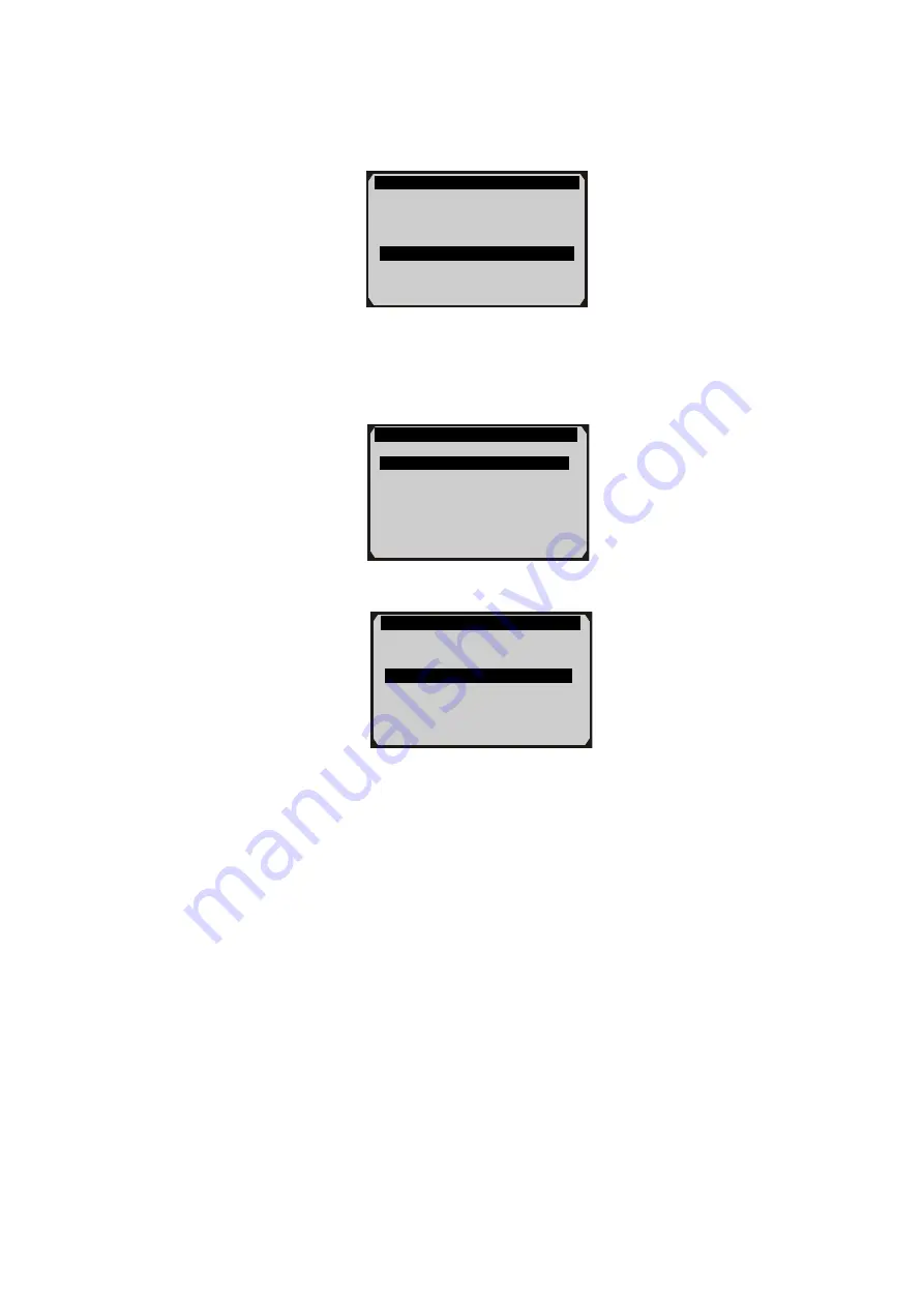
screen (Figure 6.32), and

press OK button. (Take

Audi A8

as an example)

Figure 6.32

6.

From

EPB

screen, use

UP/DOWN

scroll button to select

EPB_Audi A8,

and press

OK

button (Figure 6.33). The screen

will show as Figure 6.34.

Figure 6.33

EPB

1. EPB_Audi A8

2. EPB_Other MST

Select Mode

1. Auto Scan

2. Control Unit
3. OilReset

4. EPB

Diag. Menu

1. Read Codes

2. Erase Codes

3. Special Function

Summary of Contents for MaxiService MST505

Page 1: ...S 5 2 6 OBD II DEFINITIONS 6 3 PRODUCT INFORMATION 8 3 1 TOOL DESCRIPTION 8 3 2 SPECIFICATIONS 9 3 3 ACCESSORIES INCLUDED 10 3 4 KEYBOARD 10 3 5 POWER 10 3 6 SYSTEM SETUP 11 3 7 VEHICLE COVERAGE 15 3 8 PRODUCT TROUBLESHOOTING 16 4 PLAYBACK DATA 1 4 1 REVIEWING DATA 1 4 2 DELETING DATA 2 4 3 PRINTING DATA 2 5 OBDII DIAGNOSTICS 1 5 1 READ CODES 2 5 2 ERASE CODES 5 5 3 LIVE DATA 7 5 4 FREEZE FRAME 13...

Page 2: ...5 10 MODULES PRESENT 23 5 11 DTC LOOKUP 24 6 VW AUDI SEAT SKODA DIAGNOSTICS 26 6 1 READ CODES AND ERASE CODES 26 6 2 OIL RESET 32 6 3 EPB 40 7 PRINT AND UPDATE 51 7 1 PRINT DATA 51 7 2 SOFTWARE UPDATE 52 8 WARRANTY AND SERVICE 57 8 1 LIMITED ONE YEAR WARRANTY 57 8 2 SERVICE PROCEDURES 57 ...

Page 3: ...n front of the drive wheels and never leave the vehicle unattended while running tests Use extreme caution when working around the ignition coil distributor cap ignition wires and spark plugs These components create hazardous voltages when the engine is running Put the transmission in PARK for automatic transmission or NEUTRAL for manual transmission and make sure the parking brake is engaged Keep...

Page 4: ...e Soon The system will also store important information about the detected malfunction so that a technician can accurately find and fix the problem Here below follow three pieces of such valuable information 1 Whether the Malfunction Indicator Light MIL is commanded on or off 2 Which if any Diagnostic Trouble Codes DTCs are stored 3 Readiness Monitor status 2 2 Diagnostic Trouble Codes DTCs OBD II...

Page 5: ...usually located 12 inches from the center of the instrument panel dash under or around the driver s side for most vehicles If Data Link Connector is not located under dashboard a label should be there telling location For some Asian and European vehicles the DLC is located behind the ashtray and the ashtray must be removed to access the connector If the DLC cannot be found refer to the vehicle s s...

Page 6: ...vehicle depends on the motor vehicle manufacturer s emissions control strategy Continuous Monitors Some of the vehicle components or systems are continuously tested by the vehicle s OBD II system while others are tested only under specific vehicle operating conditions The continuously monitored components listed below are always ready 1 Misfire 2 Fuel System 3 Comprehensive Components CCM Once the...

Page 7: ...ess Status OBD II systems must indicate whether or not the vehicle s PCM s monitor system has completed testing on each component Components that have been tested will be reported as Ready or Complete meaning they have been tested by the OBD II system The purpose of recording readiness status is to allow inspectors to determine if the vehicle s OBD II system has tested all the components and or sy...

Page 8: ...rive train Malfunction Indicator Light MIL Malfunction Indicator Light Service Engine Soon Check Engine is a term used for the light on the instrument panel It is to alert the driver and or the repair technician that there is a problem with one or more of vehicle s systems and may cause emissions to exceed federal standards If the MIL illuminates with a steady light it indicates that a problem has...

Page 9: ...cted Running through a vehicle s complete drive cycle will set the readiness monitors so that future faults can be detected Drive cycles vary depending on the vehicle and the monitor that needs to be reset For vehicle specific drive cycle consult the vehicle s Owner s Manual Freeze Frame Data When an emissions related fault occurs the OBD II system not only sets a code but also records a snapshot ...

Page 10: ... Description 1 CONNECTOR Connects the scan tool to the vehicle s Data Link Connector DLC 2 LCD DISPLAY Indicates test results TFT color display 320 x 240 dpi 3 FUNCTION BUTTON Corresponds with buttons on screen for executing commands ...

Page 11: ...screens for additional data When looking up DTC it is used to change value of selected character 8 RIGHT SCROLL BUTTON When look up DTC definitions moves to next character and view additional information on next screens if DTC definition covers more than one screen views next screen or next frames of recorded data It is also used to view next trouble code when viewing DTCs 9 OK BUTTON Confirms a s...

Page 12: ...o tool and communicates between tool and vehicle 4 USB Cable Used to print retrieved data 5 Micro SD Card Used to store the data and to upgrade the scan tool 6 Protective Nylon Case Used to store the scan tool when not in use 3 4 Keyboard No solvents such as alcohol are allowed to clean the keypad or display Use a mild nonabrasive detergent and a soft cotton cloth Do not soak the keypad as the key...

Page 13: ...ormation about the scan tool 1 Language Selects the desired language 2 Unit of measure Sets the unit of measure to English or Metric 3 Beep Set Turns on off beep 4 Key Test Checks if the keyboard is working properly 5 LCD Test Checks if the LCD display is working properly 6 About Provides information of the scan tool Settings of the unit will remain until change to the existing settings is made To...

Page 14: ...e Setup English is the default language 1 From System Setup screen use the UP DOWN scroll button and LEFT RIGHT scroll button to select Language and press the OK button 2 Use the UP DOWN scroll button to select the desired language and press the OK button to save your selection and return to previous screen Figure 3 3 Figure 3 3 Unit of Measure ...

Page 15: ...on to save your selection and return to previous menu Or press the ESC button to exit without saving Beep Set The default setting is Beep On 1 From System Setup screen use the UP DOWN scroll button and LEFT RIGHT scroll button to select Beep and press the OK button 2 From Beep Set menu use the LEFT RIGHT scroll button to select ON or OFF to turn on off the beep Figure 3 5 3 Press the OK button to ...

Page 16: ...ound corresponding key on the screen should turn to red Otherwise the key is not functioning properly 3 Double press ESC to return to previous menu LCD Test The LCD Test function checks if the LCD display is working normally 1 From System Setup screen use the UP DOWN scroll button and LEFT RIGHT scroll button to select LCD Test and press the OK button 2 Look for missing spots in the red green blue...

Page 17: ... OBD II compliant including those equipped with universal protocol Control Area Network CAN It is required by EPA that all 1996 and newer vehicles cars and light trucks sold in the United States must be OBD II compliant and this includes all Domestic Asian and European vehicles A small number of 1994 and 1995 model year gasoline vehicles are OBD II compliant To verify if a 1994 or 1995 vehicle is ...

Page 18: ...he ignition back to on and continue the testing Verify the control module is not defective Operating Error If the scan tool freezes then an exception occurs or the vehicle s ECU Electronic Control Unit is too slow to respond to requests You need to do the following to reset the tool Reset the scan tool Turn the ignition off and wait for about 10 seconds Turn the ignition back to on and continue th...

Page 19: ...a screen to appear Figure 4 1 2 To review data saved in the scan function select Scan in the Review data menu To review data saved in the MST function select MST in the Review data menu Then press OK button to continue 3 Use the UP DOWN scroll button to select the desired item from Scan menu or MST menu and press the OK button Figure 4 2 Review data 1 MST 2 Scan Scan 1 Trouble scan MAKE USA FORD 2...

Page 20: ...sing You could also erase all recordings by select Delete All NOTE Don t use Delete All unless you are definitely sure what you are going to proceed 4 3 Printing Data Print option allows you to print the recorded files to your computer and then to the printer For more details please refer to chapter 7 1 Print Data Vehicle Specification Vehicle Mustang Engine Type Other Capacity 3 8L Transmission M...

Page 21: ... 4 Turn the ignition on Engine can be off or running 5 Turn on the scan tool Select OBDII from the Main Screen Figure 3 1 6 Press the OK button to wait for the Menu to appear A sequence of messages displaying the OBDII protocols will be observed on the display until the vehicle protocol is detected If the scan tool fails to communicate with the vehicle s ECU Engine Control Unit more than three tim...

Page 22: ...ect a module before testing Figure 5 2 Figure 5 2 Use the UP DOWN scroll button to select a module and press the OK button 5 1 Read Codes Reading Codes can be done with the key on engine off KOEO or with the key on engine running KOER Stored Codes are also known as hard codes which are fault codes or trouble codes that have been stored in the vehicle computer memory because the faults have reoccur...

Page 23: ...Codes are DTCs that are confirmed and are retained in the non volatile memory of the computer until the appropriate monitor for each DTC has determined that the malfunction is no longer present and is not commanding the MIL on Permanent DTC shall be stored in non volatile memory and may not be erased by any diagnostic services or by disconnecting power to ECU 1 Use UP DOWN scroll button to select ...

Page 24: ...re than one DTC is found use the UP DOWN scroll button to check all the codes If retrieved DTCs contain any manufacturer specific or enhanced codes a Manufacturer specific codes are found Press any key to select vehicle make message comes up prompting you to select vehicle manufacturer to view DTC definitions Use UP DOWN scroll button to select manufacturer and then press OK button to confirm Figu...

Page 25: ...een checked completely by a technician NOTE Erasing codes does not mean that trouble codes in ECU have been eliminated completely As long as there is fault with the vehicle the trouble codes keeps on presenting This function is performed with key on engine off KOEO Do not start the engine 1 Use the UP DOWN scroll buttons to select Erase Codes from Diagnostics Menu and press the OK button Figure 5 ...

Page 26: ... Erase Done confirmation message shows on the display Figure 5 8 Figure 5 8 If the codes are not cleared then an Erase Failure Turn Key on with Engine off message appears Figure 5 9 Figure 5 9 Erase Codes Erase Failure Turn Key on with Engine Off Press any key to continue Erase Codes Erase Done Press any key to continue Erase Codes DTCs and Freeze Data will be lost Do you wish to continue Yes No ...

Page 27: ... vehicle s computer module s 1 To view live data use the UP DOWN scroll button to select Live Data from Diagnostic Menu and press the OK button Figure 5 3 2 Wait a few seconds while the scan tool validates the PID MAP Figure 5 10 Figure 5 10 A Viewing Complete List 1 To view complete set of data use UP DOWN scroll button to select Complete List from Live Data menu and press the OK button Figure 5 ...

Page 28: ...the bottom appears when a PID is highlighted graphic information is available Select Graphics to view graph Figure 5 13 PID name current value maximum and minimum values are displayed on the screen Live Data 1 Complete List 2 Custom List Complete List Numbers of DTCs 0 Fuel system 1 status OL Fuel system 2 status Calculated load value 0 0 Engine coolant temperature 40 0 C Pause Graphics Save ...

Page 29: ...NOTE Merge Graph can be used to compare two related parameters in graphic mode which is especially convenient in the Custom List option where you could select two interacted parameter to merge and see their relationship Figure 5 14 Select Text to return to text viewing of PID data Select Save to record retrieved live data and PID graphs ...

Page 30: ...d items and click Select button to confirm The selected parameters are marked with solid squares Figure 5 15 Figure 5 15 The number to the right of selected item indicates sequence of this item If you want to deselect the item press Clear button To select all the items on the screen press Select All button To clear all the selected items on the screen press Clear All button 3 Press the OK button t...

Page 31: ...ries per vehicle Generally one frame of data is about 1 4 second or 4 frames per second 1 To record live data with the live data screen displaying select Save on the bottom The scan tool will start timing to record retrieved live data and PID graphs If you record live data under text mode following screen shows Figure 5 17 Custom List Numbers of DTCs 0 Fuel system 1 status OL Pause Graphics Save C...

Page 32: ...ic mode 2 When there is not enough memory space a warning message prompting to delete previously recorded data Figure 5 19 If you wish to delete the data select Yes and save currently retrieved data in the SD card If you do not wish to delete the data select No to return to previous screen Save Failure Memory space not enough Erase previously recorded Data Yes No ...

Page 33: ...he parameters to be duplicated for diagnostic and repair purposes 1 To view freeze frame data use the UP DOWN scroll button to select Freeze Frame from Diagnostic Menu and press the OK button Figure 5 3 2 Wait a few seconds while the scan tool validates the PID MAP 3 If retrieved information covers more than one screen use the DOWN scroll button as necessary until all the data have been shown up F...

Page 34: ...ehicle must be driven through a complete drive cycle with no trouble codes in memory Times for reset vary depending on vehicle Some latest vehicle models may support two types of I M Readiness tests A Since DTCs Cleared indicates status of the monitors since the DTCs are erased B This Drive Cycle indicates status of monitors since the beginning of the current drive cycle An I M Readiness Status re...

Page 35: ...the UP DOWN scroll button as necessary to view the status of the MIL light ON or OFF and the following monitors For spark ignition engines MIS Misfire Monitor FUEL Fuel System Monitor CCM Comprehensive Component Monitor EGR EGR System Monitor O2S O2 Sensors Monitor CAT Catalyst Monitor EVAP Evaporative System Monitor HTR O2 Sensor Heater Monitor AIR Secondary Air Monitor HCAT Heated Catalyst Monit...

Page 36: ...he following displays Figure 5 23 Figure 5 23 6 Use the UP DOWN scroll button for more PIDs if additional information is available on more than one page Or use the LEFT RIGHT scroll button to view PIDs in the previous next page Since DTCs cleared MIL Status OFF Misfire Monitoring N A Fuel system monitoring OK Comprehensive component monitoring OK Catalyst monitoring N A Heated catalyst monitor N A...

Page 37: ...ecently performed tests from the vehicle s on board computer The O2 Monitor Test function is not supported by vehicles which communicate using a controller area network CAN For O2 Monitor Test results of CAN equipped vehicles see chapter On Board Mon Test 1 Use the UP DOWN scroll button to select O2 Monitor Test from Diagnostic Menu and press OK button Figure 5 3 2 Wait a few seconds while the sca...

Page 38: ...ves and displays test results for emission related power train components and systems that are not continuously monitored The On Board Monitor Test for CAN equipped vehicles retrieves and displays test results for emission related power train components and systems that are and are not continuously monitored Test and components IDs are determined by the vehicle manufacturer In this test there are ...

Page 39: ...ID MAP 3 The scan tool shows the On Board Monitors tests for specific monitoring systems 4 From On Board Monitor Test menu use the UP DOWN scroll button to select a test to view and press the OK button Figure 5 27 If the vehicle under test does not support the mode an advisory message will be displayed on the screen Figure 5 28 On Board Monitor Test 1 Test 01 Data 2 Test 03 Data 3 Test 10 Data 4 T...

Page 40: ... Figure 5 30 For CAN equipped vehicles test results displayed can be as below Figure 5 31 On Board Monitor Test 1 EGR Monitor 2 Mis Fire Monitor Data 3 Mis Fire Cylinder 1 Data 4 Mis Fire Cylinder 2 Data 5 Mis Fire Cylinder 3 Data 6 Mis Fire Cylinder 4 Data Test 01 Data ID 11 Module 10 Test Value 0400 Min Limit 0200 Max Limit Status OK Flow Test ID 11 Module 10 Test Value 0 10 Min Limit 0 00 Max L...

Page 41: ...nd methods for stopping the test once it has been started Before starting the Component Test refer to the vehicle service manual for instructions to stop the test 1 Use the UP DOWN scroll button to select Component Test from Diagnostic Menu and press the OK button 2 Wait for the scan tool to display the Component Test menu Figure 5 32 3 If the test has been initiated by the vehicle a confirmation ...

Page 42: ...nables retrieval of Vehicle Identification No VIN Calibration ID Nos CINs Calibration Verification Nos CVNs and In use Performance Tracking on 2000 and newer vehicles that support Mode 9 1 Use UP DOWN scroll button to select Vehicle Info from the Diagnostic Menu and press OK button 2 An advisory message comes up to remind you Wait a few seconds or press any key to continue Figure 5 35 Component Te...

Page 43: ...s the OK button 5 View retrieved vehicle information on screen Figure 5 37 6 Press the ESC button to return previous menu 5 10 Modules Present The Modules Present function allows viewing of the module IDs and communication protocols for OBD2 modules in the vehicle 1 Use the UP DOWN scroll button to select Modules Present from Diagnostic Menu and press OK button Figure 5 3 Vehicle ID Number VIN 1FA...

Page 44: ...ry 1 Use the UP DOWN scroll button to select DTC Lookup from Diagnostic Menu and press OK button Figure 5 3 2 Wait for the scan tool to display the DTC Lookup screen Figure 5 39 3 Select Show and a soft keyboard will pop up Use LEFT RIGHT button and UP DOWN button to move to the desired character then press OK button to confirm Modules Present Protocol ID SAE J1850 PWM 10 Save DTC Lookup Only PCBU...

Page 45: ...ous next DTC Select Save to record code definition For manufacturer specific codes you need to select a vehicle make on an additional screen to look for DTC definitions If definition could not be found SAE or Manufacturer Specific the scan tool displays Please refer to vehicle service manual 6 Press No or ESC button to return to previous menu Trouble Codes P0005 Fuel Shutoff Valve A Control Circui...

Page 46: ...g the OBDII connector to the vehicle s DLC 4 Turn the ignition on Engine can be off or running 5 Turn on the scan tool Select MST505 from Main Screen Figure 3 1 and press OK button Wait for the Select Mode screen to appear 6 From Select Mode screen Figure 6 1 use UP DOWN scroll button to select Auto Scan and press OK button Wait for a few minutes until the following screen shows as Figure 6 2 The ...

Page 47: ...various vehicle configuration or vehicle modification 7 From Select Mode screen use UP DOWN scroll button to select Control Unit and press OK button The scan tool will list all systems and you can manually select the detecting system following onscreen instructions Select Mode 1 Auto scan 2 Control Unit 3 Oil Reset 4 EPB System 1 01 Engine 2 02 Auto Trans 3 03 ABS Brakes 4 08 Auto HVAC 5 09 Cent E...

Page 48: ...o the vehicle s DLC Verify that the module is supported Turn the ignition off and wait for about 10 seconds Turn the ignition back to on and repeat the procedure from step 5 If the LINK ERROR message does not go away then there might be problems for the scan tool to communicate with the vehicle Contact your local distributor or the manufacturer s customer service department for assistance 9 Select...

Page 49: ...may allow the scan tool to delete not only the codes from the vehicle s on board computer but also Freeze Frame data and manufacturer specific enhanced data Further the I M Readiness Monitor Status for all vehicle monitors is reset to Not Ready or Not Complete status Do not erase the codes before the system has been checked completely by a technician Function 1 Read Codes 2 Erase Codes Read Codes ...

Page 50: ...es from Function menu Figure 6 8 and press OK button Figure 6 8 If the scan tool is not connected or no communication is established with the vehicle then please refer to P47 2 After you have pressed OK button a message will come up asking you to confirm the ignition and engine status Figure 6 9 Figure 6 9 3 If you press Yes function key or OK button a warning message will come up asking your conf...

Page 51: ...u do wish to erase the codes then press Yes function key or press OK button If the codes are cleared successfully an Erase Done confirmation message shows on the display Figure 6 12 Figure 6 12 Erase Codes Erase Done Press any key to continue Erase Codes DTCs and Freeze Data will be lost Do you wish to continue Yes No Erase Codes Command Cancelled Press any key to continue ...

Page 52: ... examples actual test screens may vary for each vehicle being tested Observe the menu titles and onscreen instructions to make correct option selections IMPORTANT Always reset the engine oil life to 100 after every oil change NOTE All required work must be carried out before the service indicators are reset Failure to do so may result in incorrect service values and cause DTCs to be stored by the ...

Page 53: ...t VW and Audi vehicles being OBD II compliant can be reset manually by technicians Please select Auto Reset for other vehicles NOTE In this manner the scan tool will not communicate with the vehicle being tested 1 Select Manual Reset from the Oil Reset menu Figure 6 15 and press OK button Figure 6 15 Oil Reset 1 Manual Reset 2 Auto Reset Select Mode 1 Auto Scan 2 Control Unit 3 Oil Reset 4 EPB ...

Page 54: ... screen that appears Take VW as an example Figure 6 16 Figure 6 17 Figure 6 18 3 After entering the vehicle information the scan tool displays manual reset message as below Model 1 Cabrio 2 Golf or GTI 3 Jetta 4 Lupo 5 New Beetle Year 1 1995 2000 2 1995 2002 Vehicle 1 VW 2 Audi ...

Page 55: ...municate with the vehicle being tested If there is a linking error please refer to 3 8 product troubleshooting 1 Select Auto Reset from the Oil Reset menu and press OK button Figure 6 20 2 In the Auto Reset menu there are two options for you to select SRI Reset and Adaptation Oil Reset 1 Manual Reset 2 Auto Reset Manual Reset 1 Select Press Reset At Oil Change from the setup control for the curren...

Page 56: ...n gives an overview of ALL SRI relevant Adaptation channels You could review or enter new values for each individual item 3 Select SRI Reset function from Oil Reset menu Figure 6 21 and press OK button Then the screen shows as Figure 6 22 Figure 6 21 Figure 6 22 A From SRI Reset menu Figure 6 22 select Service Reset function and press OK button The screen will display the preset maintenance inform...

Page 57: ...d function keys work as below Finish After entering a new value use this key to save the value to the ECU Edit Press this key to pop up a soft keyboard to facilitate your input Figure 6 25 Esc Press this key to exit Service Reset Channel Description Cur Val Unit 02 Service Reminder 0 40 Service since Mileage 100km 0 41 Time since Service Day s 0 ESC OK Service Reset 02 Service Reminder 0 Finish Ed...

Page 58: ...haracter when typing NOTE The data you input must be in the reasonable range which is defined by the preset values in ECU If you enter a data out of range the tool will display a warning message Figure 6 26 B From SRI Reset menu Figure 6 22 select Mileage to Service function and press OK button The screen will display the preset maintenance information of the vehicle The information items vary wit...

Page 59: ...ll display the preset maintenance information of the vehicle The information items vary with different vehicles Figure 6 29 Figure 6 29 Mileage to Service 42 Minimum Mileage 100 To Service Finish Edit Esc Mileage to Service Channel Description Cur Val Unit 02 Service Reminder 0 40 Service since Mileage 100km 0 41 Time since Service Day s 0 ESC OK Time to Service Channel Description Cur Val Unit 02...

Page 60: ...tem you could review or enter new values as mentioned above 5 After you have finished the service settings turn the ignition off and on again to set vehicle service data in ECU 6 3 EPB This electrical parking brake EPB function has a multitude of uses to maintain the electronic braking systems safely and effectively The applications include deactivating activating the Time to Service 49 Minimum Ti...

Page 61: ...carrying out any maintenance diagnostic work on the brake system This can be done from the tool menu Only carry out maintenance work when the vehicle is stationary and on level ground Ensure that the EPB control system is reactivated after the maintenance work has been completed You may have to activate several times to position the brake pads NOTE Autel accepts no responsibility for any accident ...

Page 62: ...button Take Audi A8 as an example Figure 6 32 6 From EPB screen use UP DOWN scroll button to select EPB_Audi A8 and press OK button Figure 6 33 The screen will show as Figure 6 34 Figure 6 33 EPB 1 EPB_Audi A8 2 EPB_Other MST Select Mode 1 Auto Scan 2 Control Unit 3 OilReset 4 EPB Diag Menu 1 Read Codes 2 Erase Codes 3 Special Function ...

Page 63: ...press OK button The screen will show as Figure 6 35 Figure 6 35 9 From Select Function screen Figure 6 35 select Guided Function and press OK button The screen will show as Figure 6 36 Figure 6 36 A For Pad Change From Deactivate Brake screen select For Pad Change and press OK button Follow onscreen instructions you can execute deactivate brake activate brake adaptation and function test in Select...

Page 64: ...e screen will show as Figure 6 37 Figure 6 37 A Deactivate Brake CAUTION Deactivate the EPB system before carrying out any maintenance service work on the brakes such as changing of pads discs and calipers Use proper tools to avoid the risk of body injuries of mechanics and technicians and damage to the brake system Make sure the vehicle is properly blocked before deactivation of the system 1 To d...

Page 65: ...brakes When they are deactivated successfully a Deactivate Brake Done message comes up Figure 6 40 If the tool fails to deactivate the brakes a LINK ERROR message shows up on the display Special Function 1 Deactivate Brake 2 Activate Brake 3 Adaptation 4 Function Test Deactivate Brake Deactivate Brake Done Press any key to continue Deactivate Brake 1 For Pad Change 2 For Repair ...

Page 66: ...mer service department for assistance B Activate Brake CAUTION The EPB system must be activated after finishing the maintenance service work on the brakes Make sure the vehicle is properly blocked before activation of the system 1 To close the brake pads after finishing the maintenance service work on the brakes use UP DOWN scroll button to select Activate Brake from Special Function menu and pres...

Page 67: ...s on Audi A8 cars 1 To set new pad thickness use UP DOWN scroll button to select Adaptation from Special Function menu and press OK button Figure 6 43 2 Wait a few seconds until following screen shows as Figure 6 44 Use the three function key to change the value Activate Brake Activate Brake Done Press any key to continue Special Function 1 Deactivate Brake 2 Activate Brake 3 Adaptation 4 Function...

Page 68: ...to facilitate your input Figure 6 45 Esc Press this key to exit 3 Select Show and a soft keyboard will pop up Use LEFT RIGHT scroll button and UP DOWN scroll button to move to the desired character Take 5 as an example Figure 6 45 The three keyboard function keys work as below Adaptation Input the Brake Pad s thickness of you want The value must be between 3 and 14 mm Finish Show Esc ...

Page 69: ...ish A message will come up asking your confirmation Figure 6 46 7 Press Yes function key or OK button an Adaptation Done message comes up Figure 6 47 NOTE The data you input must be between 3 and 14mm If you enter a data out of range the tool will display a warning message to remind you to change the value D Function test Adaptation Adaptation Done Press any key to continue Input Dialog Box 5 Do y...

Page 70: ...while the device is executing the function test When they are executed successfully a Function Test Done message comes up Press any key to the previous menu Figure 6 49 Function Test Function Test Done Press any key to continue Special Function 1 Deactivate Brake 2 Activate Brake 3 Adaptation 4 Function Test ...

Page 71: ...ugh the included CD or download the applications in our website www autel com or our distributors site 2 Connect the scanner to computer with the USB cable supplied 3 Run Printer software on computer 4 Select Playback function in Main Screen of the scan tool In Scan screen use the UP DOWN scroll button to select the files you want to print Wait for the reviewing window to display Figure 4 2 then s...

Page 72: ...the textbox to the clipboard Clear Delete all data in the textbox Exit Quit the operation 7 You are also allowed to edit copy and delete the data in the Printer window NOTE The scan tool can only print text data even though the data is saved in graphic mode Note The print function is not available on Mac for the present 7 2 Software update This function allows you to update the scan tool software ...

Page 73: ...t by clicking the link provided through the mail A product registration screen opens 6 Select the product model of your tool enter the product serial number and password on the Product Registration screen and click Submit to complete the registration procedure NOTE Please use the About function to find out the Product Serial No and Register Password For details please refer to the Section 3 6 Syst...

Page 74: ...pdate window to display If you forget your password unintentionally you may always click the Forget Password to link to our website and get your password back 7 In the Update window select the items you want to install Usually you should install all available updates Figure 7 3 Generally there are two ways to update programs Batch Updating ...

Page 75: ...ed to select those suspended items again and then click the Update Selected Items button The progress will resume from the break point When the downloading is completed the downloaded programs will be installed automatically The new version will replace the old version Single Updating Find the desired updating item and click the Install button in the same line With updating in progress the Install...

Page 76: ...ow the list of programs installed Select the program s that you would delete Batch delete Select the programs that you would delete by clicking on the check boxes to the left of those items Then click the Delete button on the right side of screen Single delete Click the Uninstall button in the line of your would be deleted program A window asking Are you sure to delete the software will pop up for...

Page 77: ...dent flood lightning or if the product was altered or repaired by anyone other than the Manufacturer s Service Center 3 Autel shall not be liable for any incidental or consequential damages arising from the use misuse or mounting of the scan tool Some states do not allow limitations on how long an implied warranty lasts so the above limitations may not apply to you 4 All information in this manual...

Page 78: ...58 ...

Reviews: