background image

63

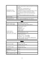
Temperature measurement
precision

±3℃ or ±3% of the reading (the larger value is used)
@Environment temperature -20℃ - 60℃

Temperature measurement
range

High gain mode: -20° - +150°
Low gain mode: 0° - +550°

EVO II Dual 640T RTK V3 Visual Camera

Image Sensor

1/1.28-inch CMOS

Effective pixels:

50 million

Lens

FOV: 85°
Equivalent focal length: 23 mm
Aperture: f/1.9
Focus range: 0.5 m ~ ∞

ISO range

Video: ISO100 - ISO64000
Photo: ISO100 - ISO6400

Digital zoom

1 - 16x (max. 4x lossless zoom)

Photo format

JPG (default)/DNG/JPG+DNG

Photo-taking mode

Single (default)/burst/AEB/periodic/HDR

Photo resolution

8192x6144(4:3)
096 × 3072 (4:3, default)
3840x2160(16:9)

Video format

MP4/MOV (MPEG-4 AVC/H.264, HEVC/H.265)

Video resolution

3840x2160P60/P50/P48/P30(default)/P25/P24
2720x1528P60/P50/P48/P30/P25/P24
1920x1080P60/P50/P48/P30/P25/P24

Max bit rate

120 Mbps

Supported file systems

FAT32/exFAT

Autel Smart Controller V3

Maximum transmission
distance (unobstructed, free
of any interference)

15 km(FCC), 8 km(CE)

*Operating frequency

902-928 MHz(FCC)
2.400-2.4835 GHz
5.725-5.850GHz (Countries except for Japan)
5.650-5.755GHz (Japan)

Summary of Contents for EVO II RTK V3 Series

Page 1: ...1 EVO II RTK Series V3 User Manual 2022 09 ...

Page 2: ... trademarks of Autel Robotics Co Ltd hereinafter referred to as Autel Robotics in China and other countries regions All other products and company names mentioned in this User Manual are registered trademarks of their respective holders Copyright No part of this Manual may be copied or transmitted in any form or by any means electronic mechanical photocopying recording or otherwise without the pri...

Page 3: ...devices When the Autel Explorer App is connected to the aircraft and the backup option is turned on flight logs and flight remote sensing data will be automatically uploaded and saved in the Autel Robotics data server All flight remote sensing data and flight logs can be uploaded automatically only when the flight log backup option is turned on Unless the user explicitly grants permission through ...

Page 4: ...cs is not responsible for any repercussions caused by the use of third party batteries or charging devices Do not disassemble scratch squeeze bend puncture cut twist or otherwise intentionally damage the battery Otherwise it may cause fire explosion leakage or other hazards Once the battery begins to bulge smoke leak or show any other signs of damage stop using it immediately and immerse it in a c...

Page 5: ...rp objects water metal or reactive chemicals Storing the battery at extreme temperatures will shorten its life If the battery is not used for more than 6 days it should be stored at a temperature of 10 C to 30 C If left unused for an extended period of time the service life of the battery will be shortened Battery Disposal Please fully discharge the battery before the disposal Dispose of the batte...

Page 6: ...n taking off and landing the aircraft stay away from people vehicles and other moving objects Do not let the aircraft leave your sight Do not let the aircraft approach the water when flying it When a low battery alarm occurs do not cancel the auto return process Otherwise the aircraft may not be able to return to the home point due to insufficient battery power When the Autel Explorer App displays...

Page 7: ...7 Store the aircraft and its accessories in a cool dry place The aircraft should be kept away from water and heat sources The recommended storage temperature for the aircraft is 22ºC to 28ºC ...

Page 8: ...4 2 1 3Aircraft Battery 15 2 1 4Gimbal and Camera 19 2 1 5Flight Control System 24 2 1 6Intelligent Flight Features 26 2 1 7Omnidirectional Binocular Vision Sensing System 28 2 2 Remote Controller 32 2 2 1Component Description 32 2 2 2Use the Remote Controller 34 2 3 RTK module 37 2 3 1Use the RTK Module 37 2 4 Autel Explorer App 38 2 4 1Mission 38 Chapter 3 Flight Preparations 42 3 1 Prepare the ...

Page 9: ...the Aircraft with the Remote Controller 44 3 3 Prepare the Aircraft 45 3 3 1Unfold the Aircraft 45 3 3 2Propeller 45 3 3 3Compass Calibration 46 Chapter 4 Flight Operation 49 4 1 Pre flight Checklist 49 4 2 Flight Operation 49 4 2 1Takeoff Mode 2 49 4 2 2Control with Command Sticks Mode 2 50 4 2 3Landing 52 Chapter 5 Maintenance and Service 53 5 1 Firmware Updates 53 5 2 Troubleshooting 54 5 3 Sto...

Page 10: ...10 5 5 Customer Service 56 5 5 1Technical Support 56 5 5 2Maintenance Service 57 Chapter 6 Appendix 58 6 1 Unlock No Fly Zones 58 6 2 Specifications 59 ...

Page 11: ...s included in the packing box If anything is missing contact Autel Robotics customer support or local retailers 2 User Manual Teaches you how to operate the product in a skillful way 3 Quick Guide Provides basic knowledge about how to operate the product 4 Disclaimer and Safety Operation Guidelines Provides instructions on how to safely operate the product 5 Battery Quick Guide Provides basic know...

Page 12: ...eal time transmission of 1080P video images The aircraft adopts a foldable fuselage design making it portable and convenient to fly With a maximum transmission distance of 15 km FCC the aircraft offers a flight time of up to 36 minutes and can reach a top speed of up to 72 km h The body of the aircraft has 12 visual sensors providing omni directional obstacle avoidance The Autel Explorer App provi...

Page 13: ...13 Power Button Rear LED Indicator Rear Vision System Left Vision System SD Card Slot Right Vision System USB C Port Aircraft Battery Linking Button Indicator Air Outlet ...

Page 14: ...and linking button indicator Please ensure that the protective cover is closed during the flight 2 1 2 Flight Status Indicator The aircraft has an LED indicator at the end of each arm The front LEDs glow solid red to identify the orientation of the nose of the aircraft The rear LEDs show the current flight status of the aircraft The following table describes the meaning of ...

Page 15: ...quickly There is no connection between the aircraft and the remote controller R Flash slowly Low battery warning R Flash quickly Critical low battery warning R Normally on Critical error or IMU error RY Flash alternately Compass error requiring calibration magnetic interference Compass Calibration Y Flash quickly Prepare to calibrate the compass The aircraft is being calibrated G Normally On Calib...

Page 16: ...f you have already installed the battery onto the aircraft the two LED indicators on the nose and tail of the aircraft will flash 5 times indicating that the aircraft is being shut down Remove the battery from the aircraft when all power indicators are turned off Check the battery level When the battery is turned off press the power button for 1s and quickly release it to check the battery level T...

Page 17: ...etting and the discharge takes about 2 3 days Although there is no prompt message indicating that the battery is self discharging you may notice that the battery feels slightly hot This is normal You can customize the battery discharge threshold using the Autel Explorer App Sleep Mode Protection If the battery is low it automatically enters the sleep mode to prevent damages In this mode there is n...

Page 18: ... Saver Mode The battery will be turned off if no operation is performed within 30 minutes Communication When the battery is in use it is continuously synchronized with the aircraft for providing real time information including the voltage capacity current and temperature Ultra Low Power Mode To save electricity when the battery is idle for 6 days and the voltage is lower than 11 6 V the battery en...

Page 19: ...ar and stable images To ensure that the gimbal can work properly the gimbal temperature must keep between 10ºC and 50ºC You can pitch or tilt the gimbal 30º degrees to 90º degrees using a dial on the remote controller or an Autel Explorer App 1 EVO Ⅱ Pro RTK V3 Gimbal MCU Mounting Plate Pitch Motor Vibration Absorber Roll Motor Camera Yaw Motor Filter ...

Page 20: ...e the gimbal protective cover before you turn on the aircraft Otherwise the gimbal motor and circuit may be damaged When you turn on the aircraft the gimbal will automatically rotate to perform self check and calibration Make sure that there is no object near the gimbal that prevents the movement of the gimbal 3 Gimbal Operation Mode Stabilized mode The roll axis remains horizontal and the pitch a...

Page 21: ...tment facing upwards 2 Use a T6 screwdriver to loosen the two screws that are fixing the gimbal protective cover and then remove the protective cover Use a cross screwdriver to loosen the screws that are fixing the FPC connector and then pull the connector cable port from the slot 3 Gently pinch the tail of the vibration absorber with your thumb and index finger Slide the gimbal backwards and upwa...

Page 22: ...line Important Make sure that the ring at the front of the gimbal is aligned with the two pins in the gimbal compartment at the nose of the aircraft Make sure that the gimbal is at the same height as the slot of the gimbal compartment 2 Insert the connector cable port into its slot and gently push it to the end Place the cover on the top of the gimbal compartment and re tighten the cover with a cr...

Page 23: ...t AEB Periodic and HDR Images are saved in DNG or JPG format while videos are recorded in MOV or MP4 format Images and videos can be stored in the SD card or the storage device of the aircraft EVO Ⅱ Dual 640T RTK V3 Two kind of cameras are provided 4k visual cameras and an infrared thermal imaging camera The thermal imaging camera can work in visual light infrared light or in Picture in Picture mo...

Page 24: ... or UHS 3 Micro SD card Warning To protect files on your aircraft turn off the aircraft before you remove the micro SD card 8 Transfer Files to Your Computer To transfer photos and videos to your computer connect the aircraft to your computer through a USB C port as shown below 2 1 5 Flight Control System EVO Ⅱ RTK Series V3 aircraft provides stable and convenient flight control through its built ...

Page 25: ...PS signals and flight conditions Flight Mode Flight Mode Description GPS mode The aircraft will activate the GPS mode once it detects a sufficient GNSS signal In GPS mode with the assistance of the front and rear vision systems the aircraft can locate and avoid obstacles GPS provides stable and smooth flight control and supports features such as return to home and failsafe ATTI mode The aircraft a...

Page 26: ...ntroller to exit the auto return mode and regain the control over the aircraft Important The default altitude for returning to the home point is 30 meters If the auto return feature is activated when you fly your aircraft at a lower altitude the aircraft will ascend to the default altitude of 30 meters and then return to the home point If you activate the auto return feature when the aircraft is w...

Page 27: ...al low battery warning and the aircraft will automatically land in the current place For any emergency press the Pause button to stop landing and manually fly the aircraft to the nearest safe landing point Note When the battery level of the aircraft reaches 25 low battery warning if the horizontal distance between the aircraft and the home point is less than 50 meters 150 ft the aircraft will not ...

Page 28: ...en the aircraft and potential obstacles Once an obstacle is detected the system will stop the aircraft from flying forwards The binocular vision systems on the front rear and bottom are also equipped with a Starpoint positioning system This system uses the ultrasonic sensor to calculate the altitude of the aircraft and is combined with the binocular vision camera to obtain the location information...

Page 29: ...29 ...

Page 30: ... signal is weak or the vision positioning is not available for example small visible texture on the object surface or the aircraft is flying at an altitude above 12 meters you should be extremely careful The binocular vision sensing systems and Starpoint locating systems are affected by the brightness and texture of the objects below the aircraft Avoid flying the aircraft above the following surfa...

Page 31: ...ds to set yourself as the target hold your arms flat to take a photo and raise one arm to start or stop recording Accurate Landing The accurate landing feature uses the binocular vision system on the bottom of the aircraft to record the takeoff location When the aircraft is returning to the home point or landing vision algorithms are used to calculate the distance between the aircraft and the take...

Page 32: ...upward or downward movement of the aircraft 2 Gimbal dial Adjusts the gimbal s pitch or tilt angle 3 Video recording button Start stop video recording 4 Custom key C1 Uses the Autel Explorer App for feature settings 5 Air outlet Used for heat dissipation for the remote controller 6 HDMI port Outputs image transmission signals 7 Type C port Used for charging the remote controller 8 USB port Expanda...

Page 33: ...rts tapping operations 17 Pause button Instructs the aircraft to stop flying and hover in the current place or resume flying 18 Auto takeoff return button Instructs the aircraft to take off or return to the takeoff point 19 Microphone Receives audio recordings 20 Horn hole Plays recordings or messages about aircraft statuses 21 Standard 1 4 interface Used for connecting to the tripod ...

Page 34: ... indicator is normally on battery level 25 2 LED indicators are normally on battery level 50 3 LED indicators are normally on battery level 75 4 LED indicators are normally on battery level 100 2 Turn on off Press the power button for 2s to turn the remote controller on off 3 Charge the remote controller Connect one end of the charging cable to the USB port on the top of the remote controller and ...

Page 35: ...t communications Note Do not use other communication devices of the same frequency band at the same time to prevent interference with the signals of the remote controller In practices when the image transmission signals are weak the Autel Explorer App will display prompt messages Adjust the antennas according to the prompted instructions and ensure that the aircraft is in the place for best commun...

Page 36: ...r or perform the following steps 1 Turn on the remote controller Go to App camera page Then click Setting Remote Controller Remote Controller Calibration Two 米 shaped and two horizontal bars will appear on the screen representing the left and right command sticks and dials respectively 2 Stick calibration Push and hold the stick one by one in eight directions until you hear a beep each time 3 Dial...

Page 37: ...twork 1 Make sure that the remote controller has already been connected to the aircraft and the network 2 Go to the camera page of the Autel Explorer App click the Settings button in the upper right corner select RTK and then set the RTK service type to Network RTK Autel Robotics has already provided the designated network RTK package You do not need to purchase it within the validity period If th...

Page 38: ...ight speed the flight speed of the aircraft when it is flying to the waypoint The aircraft will adjust the flight speed to the preset value on the way to the waypoint Click Waypoint select Flight Speed and slide left or right to change the value Action Click Waypoint select Action and set the waypoint actions and camera actions Waypoint actions include Fly Over and Hover A If you select Fly Over t...

Page 39: ... the menu on the bottom to modify parameters Rectangular mission generate a rectangular region The aircraft will fly in a bow shaped route if the double grid is disabled This is suitable for collecting orthophoto data The aircraft will fly in a route whose shape is like a pound key if the double grid is enabled This is suitable for 3D modeling Polygon mission generate a polygon shaped region The a...

Page 40: ...desert field vegetation etc increasing the overlap is conducive to image stitching and processing in the later stage GSD It refers to the actual physical size that a pixel represents The smaller the value the more clear the image Important If one of the following errors occur the mission automatically ends and the aircraft will perform the corresponding operations Low battery A message is displaye...

Page 41: ...re displayed in the order of the creation time The most recently saved missions are at the top of the list while the ones that are saved earlier ago are at the bottom In addition you can search for a file name to find the corresponding historical mission ...

Page 42: ...attery 2 Insert the battery into the battery compartment as shown in the figure on the right You will hear a clicking sound when the battery is installed correctly 3 1 2 Remove the Aircraft Battery 1 Turn the aircraft battery switch to off before you remove the battery 2 Press and hold the clips on both sides of the battery and slowly pull the battery out 3 1 3 Charge the remote controller 1 Batte...

Page 43: ...ing charging Green LED is normally on Green LED flashes 2 Remote controller Insert the Type C cable into the Type C port of the remote controller Note Fully charge the batteries of the aircraft and remote controller before the flight It takes about 90 minutes to fully charge the aircraft and about 120 minutes to fully charge the remote controller Disconnect the charger from the battery of the airc...

Page 44: ... the Remote Controller Turn on off Press and hold the power button for 2 seconds until you hear a short beep Important Always turn on the remote controller before you turn on the aircraft Always turn off the aircraft before you turn off the remote controller 3 2 3 Pair the Aircraft with the Remote Controller By default the remote controller is linked to the aircraft before delivery When you need t...

Page 45: ...ed to put the protective cover back on the gimbal to prevent damage 2 Extend the Arms and Propeller Always unfold the aircraft arm before you turn on the aircraft Unfold the front arm first and then the rear arm Important Turn off the aircraft before you fold the arms 3 3 2 Propeller EVO II RTK Series V3 aircraft uses a propeller that is easy to remove Warning Turn off the aircraft before you inst...

Page 46: ...unting plate with no white mark Legend description Locking direction Rotate the propeller in the direction as shown in the figure to secure it Unlocking direction Rotate the propeller in the direction as show in the figure to remove it 2 Remove the Propeller 1 Turn off the aircraft 2 Press the propeller firmly and rotate it in the unlocking direction to remove the propeller Important Before the fl...

Page 47: ...bration results Keep it away from underground and overhead power lines Do not carry ferromagnetic materials with you during calibration such as keys or magnetic jewelry Keep it away from all electronic devices such as mobile devices that may interfere with calibration 3 Calibration Procedure 1 Turn on the aircraft and remote controller launch the Autel Explorer App go to the camera page and click ...

Page 48: ...48 ...

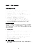
Page 49: ...and wind speed Check whether the camera lens of the aircraft and sensors are clean 4 2 Flight Operation The aircraft provides three command stick modes mode 1 mode 2 and mode 3 In each mode you can control the aircraft in a different way By default mode 2 is used You can switch the modes using the Autel Explorer App We recommend that beginners use mode 2 1 Basic Procedure 1 Place the aircraft in a...

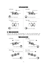
Page 50: ...that the aircraft cannot take off 4 2 2 Control with Command Sticks Mode 2 Tip If you are the first time to control the aircraft move the stick gently until you are familiar with the operations 1 Left command stick Push the stick upwards and downwards to ascend or descend the aircraft Push the stick to the left or right side to control the orientation of the aircraft ...

Page 51: ... the left or right Left view Left view Top view Ascend Push upwards Push downwards Descend Push to the left Push to the right Nose turning right Nose turning left Left command stick Left view Rear view Rear view Forwards Push upwards Push downwards Backwards Push to the left Push to the right Move to the right Move to the left Right command stick Top view Left view ...

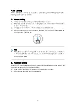
Page 52: ... aircraft 4 After the aircraft lands on the ground push the left command stick all the way until the motor is turned off Note When the low battery warning 25 is displayed the LED indicator on the back of the aircraft flashes red In this case you must immediately let the aircraft to land on a safe place 2 Automatic landing When one of the following errors occur failsafe will be triggered and the ai...

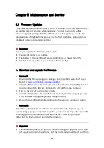
Page 53: ...official website of Autel Robotics www autelrobotics com download 161 2 Insert the SD card into the computer and extract the downloaded files into the root directory of the SD card Remove the SD card from the computer 3 Turn on the aircraft and remote controller 4 Insert the SD card into the aircraft to automatically start the upgrade process You can check the upgrade process through the app 5 Res...

Page 54: ...aircraft cannot take off after you start the motor check the following Check whether the aircraft is in a No Fly Zone Check whether the aircraft is placed on a flat surface Question 4 Why is the flight time shortened The common causes are low temperature and wind speed Question 5 There is no response from the remote controller when pairing it with the aircraft Check whether there is a metal object...

Page 55: ...e aircraft takes off However if the ground does not have any texture or the camera on the rear of the aircraft is damaged this feature cannot work properly Question 11 The omnidirectional binocular vision sensing system cannot work properly Restart the aircraft and check whether the system can work properly this time Question 12 The video is tilted during the flight Place the aircraft horizontally...

Page 56: ...ers who purchase the products from authorized retailers Autel Robotics guarantees that in normal use the Autel Robotics product you buy is free from defects in material or workmanship The warranty period for this product starts on the day you received the product If you cannot provide a valid proof of purchase such as a purchase invoice the warranty start date will be defined as 90 days after the ...

Page 57: ...ntenance please send an email to after sale autelrobotics com for customer support Note All content of the product may be deleted during maintenance We recommend that you create a backup copy of the data in the product before delivering the product for warranty service ...

Page 58: ... the flight This ensures that the aircraft complies with the lawful requirements on flight zones Note You must ensure that you abide by all relevant flight rules and regulations If you want unlock a No Fly Zone visit the official website of Autel Robotics and follow the instructions on the page to submit an application www autelrobotics com page noflight ...

Page 59: ...tes Maximum flight speed 20 m s in ludicrous mode Maximum ascent speed 8 m s in ludicrous mode Maximum descent speed 4 m s in ludicrous mode Maximum flight altitude 7000 meters Wind resistance 12 m s Take off and landing Operating temperature 10 40 Operating frequency 902 928 MHz FCC 2 400 2 4835 GHz 5 725 5 850GHz Countries except for Japan 5 650 5 755GHz Japan Transmission power 900M FCC ISED 31...

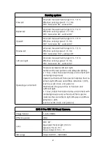
Page 60: ...ss 10 or UHS 3 GNSS Single frequency and highly sensitive GNSS GPS BeiDou Galileo Asia GPS GLONASS Galileo Other regions Multi frequency multi system and high precision RTK GNSS Used frequency points GPS L1 L2 GLONASS L1 L2 BeiDou B1 B2 Galileo E1 E5 First positioning time 50 s Positioning accuracy Vertical 1 5 cm 1 ppm RMS Horizontal 1 cm 1 ppm RMS 1 ppm For every 1 km increase in distance the ac...

Page 61: ...rating environment Forward backward left and right Surface with clear patterns and adequate lighting 15 lux indoor fluorescent lamp environment with normal light exposure Upward surface built from special materials that can reflects light diffusely and diffuse reflection 20 such as walls trees and persons Downwards the ground has rich texture and sufficient light 15 lux indoor fluorescent lamp env...

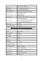
Page 62: ... P50 P48 P30 P25 P24 Max bit rate 120 Mbps Supported file systems FAT32 exFAT EVO II Dual 640T RTK V3 Thermal Imaging Camera Infrared thermal imaging sensor Uncooled infrared focal plane detector made out of vanadium oxide Sensor resolution 640x512 Wavelength 8 14 μm Focal length 13 mm FOV H33 V26 Pixel size 12 μm Digital zoom 1 16 times Accurate distance for temperature measuring 2 20 meters Phot...

Page 63: ...4x lossless zoom Photo format JPG default DNG JPG DNG Photo taking mode Single default burst AEB periodic HDR Photo resolution 8192x6144 4 3 096 3072 4 3 default 3840x2160 16 9 Video format MP4 MOV MPEG 4 AVC H 264 HEVC H 265 Video resolution 3840x2160P60 P50 P48 P30 default P25 P24 2720x1528P60 P50 P48 P30 P25 P24 1920x1080P60 P50 P48 P30 P25 P24 Max bit rate 120 Mbps Supported file systems FAT32...

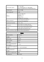
Page 64: ...ting temperature 20 40 Dimensions 303 190 87 mm folded antennas 303 273 87 mm extended antennas Weight 1150 g without the protective cover 1250 g with the protective cover Satellite positioning module GPS GLONASS Galileo BeiDou Battery Battery capacity 7100 mAh Voltage 11 55 Battery type LiPo 3S Battery energy 82 Wh Net weight 365 g Environment temperature for charging 5 45 Temperature humidity fo...

Page 65: ...65 Charger Input 100 240V 50 60 Hz 1 5A Output 13 2V 5A 5V 3A 9V 2A 12V 1 5A Voltage 13 2V Rated power 66W Note The used frequency band varies in different countries and regions ...

Reviews: