background image

 8 

Programming

- 27 -

LIMM&SA0-00.fm

 8.3

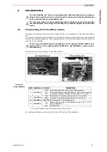
Programming the master board E16B14AC

Dip switch programming has to correspond to that given in the technical data sheet and must 
not be modified.

 8.4

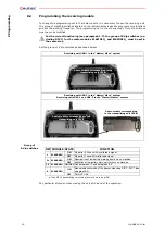
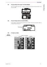
Programming the bus board E16RI02_

Autec programs this bus board and programming is recorded in the data memory that configures 
outputs of the receiving unit.

 8.5

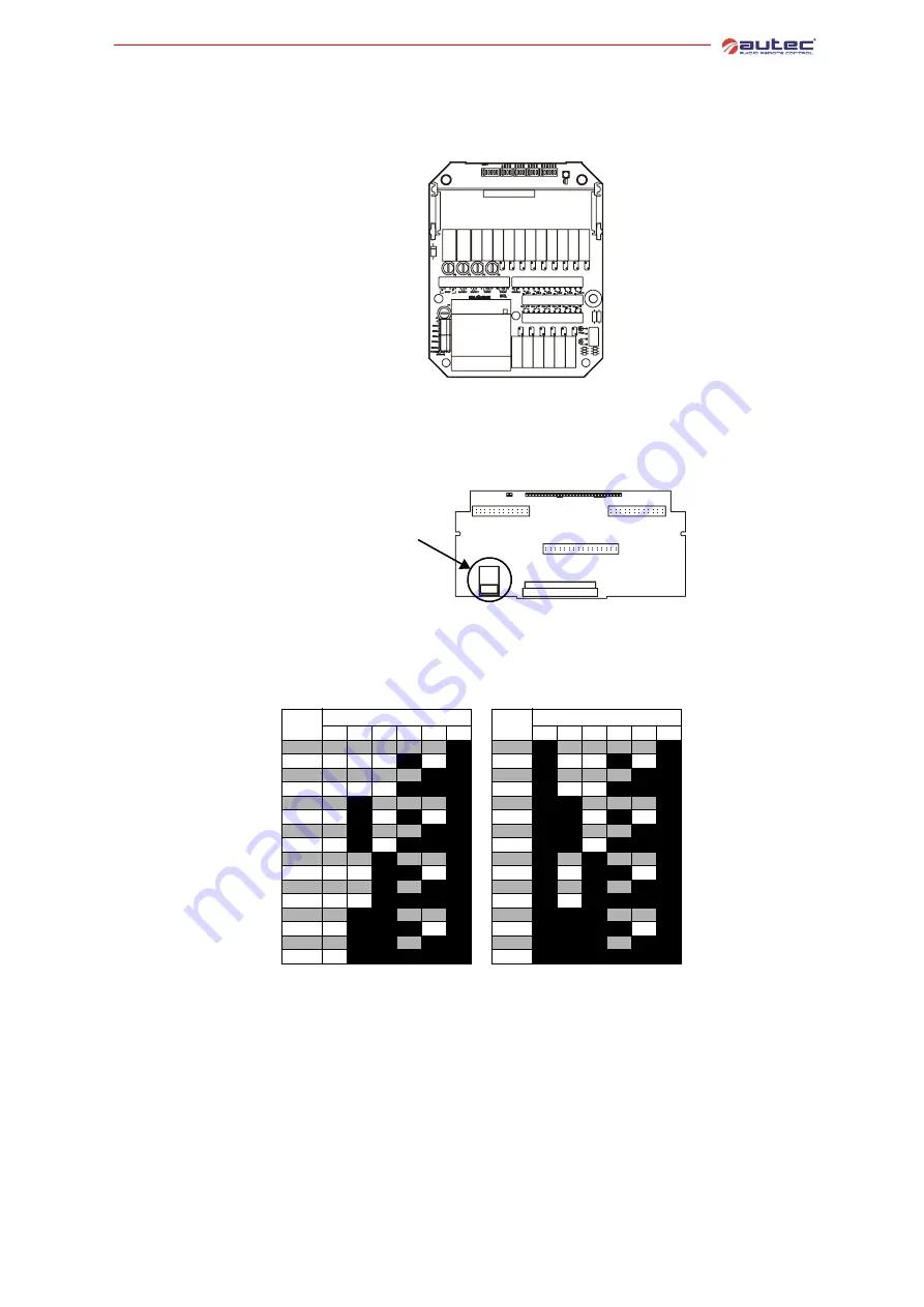
Frequency tables

Settable 

frequencies

Data memory

E16STXUS1 and E16SRXUS1

MHz

DIP SWITCH

MHz

DIP SWITCH

3

4

5

6

7

8

3

4

5

6

7

8

902.150 OFF OFF OFF OFF OFF

ON

915.350

ON

OFF OFF OFF OFF

ON

903.050 OFF OFF OFF

ON

OFF

ON

916.250

ON

OFF OFF

ON

OFF

ON

903.850 OFF OFF OFF OFF

ON

ON

917.050

ON

OFF OFF OFF

ON

ON

904.650 OFF OFF OFF

ON

ON

ON

917.850

ON

OFF OFF

ON

ON

ON

905.525 OFF

ON

OFF OFF OFF

ON

918.675

ON

ON

OFF OFF OFF

ON

906.325 OFF

ON

OFF

ON

OFF

ON

919.525

ON

ON

OFF

ON

OFF

ON

907.175 OFF

ON

OFF OFF

ON

ON

920.375

ON

ON

OFF OFF

ON

ON

907.975 OFF

ON

OFF

ON

ON

ON

921.175

ON

ON

OFF

ON

ON

ON

908.850 OFF OFF

ON

OFF OFF

ON

922.050

ON

OFF

ON

OFF OFF

ON

909.650 OFF OFF

ON

ON

OFF

ON

922.850

ON

OFF

ON

ON

OFF

ON

910.450 OFF OFF

ON

OFF

ON

ON

923.650

ON

OFF

ON

OFF

ON

ON

911.250 OFF OFF

ON

ON

ON

ON

924.450

ON

OFF

ON

ON

ON

ON

912.125 OFF

ON

ON

OFF OFF

ON

925.325

ON

ON

ON

OFF OFF

ON

912.925 OFF

ON

ON

ON

OFF

ON

926.175

ON

ON

ON

ON

OFF

ON

913.775 OFF

ON

ON

OFF

ON

ON

926.925

ON

ON

ON

OFF

ON

ON

914.525 OFF

ON

ON

ON

ON

ON

927.725

ON

ON

ON

ON

ON

ON

Summary of Contents for Modular series

Page 1: ...Modular Series Master Slave system Master Master system User Manual ...

Page 2: ......

Page 3: ...Modular Series Master Slave system Master Master system User Manual ...

Page 4: ...ase specify the serial number of the related radio remote control Contact AUTEC if any of the instructions and or warnings given in this manual is not clear The information contained in this manual is subject to modification without notice and is not binding No part of this manual may be reproduced in any form or by any means without written permission of Autec including recording and photocopying...

Page 5: ...unit 14 3 6 Warnings for the maintenance of the receiving unit 14 3 7 External signal lights of the receiving unit 15 3 8 Internal signal lights of the receiving unit 16 4 Operating mode of Master Slave 17 4 1 Command Take Release 2 or Release 2 17 4 2 Power on and start up 18 5 Operating mode of Master Master 19 5 1 Command Take Release 19 5 2 Power on and start up 20 6 Operating mode of the tran...

Page 6: ...sly stops the whole system thanks to the passive emergency function passive stop The radio remote controls of the Modular series are equipped with a dual channel pro cessing that protects the system radio remote control machine when it is in neu tral standstill position from unintended movements caused by possible radio remote control single faults Such safety function is only possible if the wiri...

Page 7: ...itting units called UTX M and UTX S and of two receiving units called URX 1 and URX 2 A Master Master system is designed and implemented so that all its units al ways work in the same working application and they cannot be split into two in dependent radio remote controls The transmitting unit UTX M can work in single mode namely it can work with either of the two receiving units either URX 1 or U...

Page 8: ...levision reception which can be determined by turning the equipment off and on the user is encour aged to try to correct the interference by one or more of the following measures reorient or relocate the receiving antenna increase the separation between the equipment and receiver connect the equipment into an outlet on a circuit different from that to which the receiver is connected Consult the de...

Page 9: ...nt receiving units if the remote controlled machines are not within the same visual field the operator should always be able to know which machines are being activated in a particular moment i e through an acoustic or light signal Loss of radio linkIt must be taken into account the fact that radio link with one or more receiving units can be lost due to radio interferences power supply disconnecti...

Page 10: ...ules see chapter 8 Frequencies for the Master Slave Frequencies set in a Master Slave system must undergo the following rules the transmitting unit UTX M and the transmitting unit UTX S must work at two different frequencies the receiving unit URX 1 must have the same working frequency as the trans mitting unit UTX M both working frequencies of the receiving unit URX 2 must be set as explained in ...

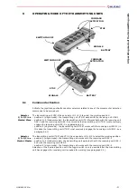
Page 11: ...sing C2 toggle switch G START pushbutton C3 keyswitch selector H battery Power supply battery pack MBM06MH a NiMH 7 2 Vdc Antenna internal Battery capacity with fully charged battery continuous use at 20 C 15 hours Low battery warning 3 5 min Housing PA 6 20 fg Protection degree NEMA 4 IP65 Dimensions 3 3 x 10 2 x 2 85 x 260 x 50 mm Weight 1 4 lbs 650 g Transmitting power frequency 433 MHz meets F...

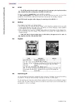
Page 12: ...ate in the battery housing H starting keyswitch H F E D C B A G Power supply battery pack MBM06MH a NiMH 7 2 Vdc Antenna internal Battery capacity with fully charged battery continuous use at 20 C 14 hours Low battery warning 3 5 min Housing PA 6 20 fg Protection degree NEMA 4 IP65 Dimensions 10 x 6 7 x 5 255 x 170 x 126 mm Weight 2 9 lbs 1 3 kg Transmitting power frequency 433 MHz meets FCC Part ...

Page 13: ... the battery Never leave the transmitting unit unguarded when the starting keyswitch is in serted Switch on or use the transmitting unit only when starting work improper use could be hazardous Never switch on or use the transmitting unit in closed spaces with the machine not in sight or outside the typical working range When operating in tandem mode always stay within the working range of both rec...

Page 14: ... following manual are respected Receiving unit technical data Supply voltage POWER SUPPLY A cable gland opt plug Drilling template B identification plate G 5 8 148 mm C technical data plate H 4 6 116 mm D POWER ENABLE light L 10 253 mm E antenna M 10 253 mm F ENABLED lights if present Min Nom Max Voltage Vac 18 25 30 25 35 42 36 50 62 70 110 132 150 230 250 Frequency Hz 50 60 Absorbed power VA 11 ...

Page 15: ...ing module corresponding to the transmitting unit UTX M must have the same working frequency as the transmitting unit UTX M the radio receiving module corresponding to the transmitting unit UTX S must have the same working frequency as the transmitting unit UTX S See paragraph 8 4 to program the bus board E16RI02D Temperature Relative Humidity Air Pressure Working Class 4K4H 5 F to 160 F 20 C to 7...

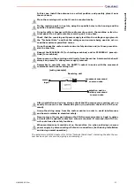
Page 16: ...ram the bus board E16RI02D 3 4 General warnings for the installation of the receiving unit FAILURE TO COMPLY WITH THE FOLLOWING WARNINGS MAR RESULT IN SERI OUS INJURY OR DEATH TO PERSONNEL AND DAMAGE TO EQUIPMENT Installation must only be carried out by qualified people and in accordance with installation country rules The installer must always respect the following warnings Place the receiving un...

Page 17: ...itch should always be present to allow power supply removal Remember to carefully wire the SAFETY contact in series with the movement commands inside the receiving unit After installation and wiring always check that the manoeuvres carried out are exactly the same as the commands given in particular check the STOP com mand Group the wiring away from the radio modules in order to avoid interference...

Page 18: ...in the various situations Radio link Install the two receiving units and their antennas so that the radio link is facili tated minimum distance between the two units or antennas must be more than 3 meters maximum distance between the two units or antennas must be shorter than twice the typical working range of the radio remote control Alignment control While operating in tandem mode if unusual adv...

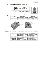
Page 19: ...nsmitting unit UTX M the receiving unit URX 2 is free from the transmitting unit UTX S Steady light the receiving unit URX 2 is engaged by the transmitting unit UTX M the receiving unit URX 2 is engaged by the transmitting unit UTX S ENABLED UTX M ENABLED UTX S Signal type ENABLED UTX M ENABLED UTX S Light off in the unit URX 1 the receiving unit URX 1 is free from the transmitting unit UTX M the ...

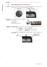
Page 20: ...e receiving mod ule that indicate 1 power supply on 2 radio link on 3 frequency scanning search LEDs in the bus board Two diagnostic LEDs are present both on the bus board E16RI02B and on the bus board E16RI02D indicating The lights ENABLED UTX M and ENABLED UTX S see paragraph 3 7 are also present in the bus board E16RI02D Mother board E16RI02_ bus board A A 1 2 3 LEDs Meaning LED 3 green power s...

Page 21: ...ansmitting unit UTX S In order to release the receiving unit URX 2 activate the command Take Release 2 again An OFF status of the lamp or horn ENA M confirms that the unit has been released When the transmitting unit UTX M is switched off but has not released the receiving unit URX 2 the lamp or horn ENA M stays ON blinking slowly Transmitting unit UTX S The transmitting unit UTX S has a Release 2...

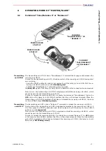
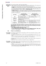
Page 22: ... allows the transmitting unit UTX M to work with the receiving unit URX 1 only single mode 1 To switch on the transmitting unit UTX M insert the starting keyswitch and turn it to I po sition 2 To start the radio remote control functions press the START pushbutton for 3 4 seconds After start up the green signalling LED in the transmitting unit always lights up In order to engage the receiving unit ...

Page 23: ...itting unit In order to release the receiving unit activate once again the corresponding Take Release command An OFF status of the related lamp or horn confirms that the unit has been released When a transmitting unit is switched off without having released a receiving unit the related lamp or horn is ON blinking slowly Receiving units status The two receiving units have three working modes free i...

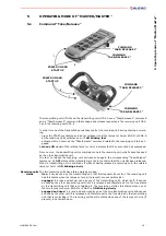
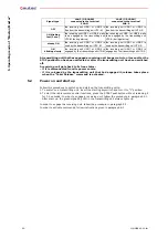
Page 24: ...t up the green signalling LED in the transmitting unit always lights up In order to engage the receiving unit follow the procedure in paragraph 5 1 In order to activate commands follow instructions given in paragraph 6 1 Signal type LAMP OR HORN connected to the terminal ENA M LAMP OR HORN connected to the terminal ENA S OFF the receiving unit URX 1 or URX 2 is free from the transmitting unit UTX ...

Page 25: ...in this case the transmitting unit UTX M must previously engage the receiving unit URX 2 see paragraph 4 1 position 2 single mode the transmitting unit UTX M works with the receiving unit URX 2 in this case the transmitting unit UTX M must previously engage the receiving unit URX 2 see paragraph 4 1 Selector 1 1 2 2 in a Master Master The transmitting units UTX M and UTX S have a selector 1 1 2 2 ...

Page 26: ...e battery from the charger if the battery is not removed the charger switches to trickle charging Read and stick to the warnings given in the battery charger manual in order to lengthen the life of the battery itself 6 4 Signals a b 6 5 Switching off The transmitting unit should be switched off each time work is stopped by turning the starting keyswitch to O position and extracting it always put t...

Page 27: ... or steam cleaners 2 store the transmitting unit in clean and dry areas 3 make sure that the gaskets bellows and caps of the joysticks selectors and pushbuttons are intact soft and elastic 4 make sure that the battery housing and the battery contacts are always clean 5 check structural integrity of the transmitting unit 6 make sure that the panel symbols can be easily recognised and replace the pa...

Page 28: ... the receiving unit has been disconnected from the power source and that the battery has been removed from the transmitting unit before carrying out any special maintenance work Any fault should be repaired by authorised personnel contact Service using original Autec spare parts only The following radio remote control data must be communicated in order to make interventions faster and more reliabl...

Page 29: ...fied For the correct functioning see paragraph 1 7 the group of 8 dip switches ex cluding DIP 1 for the radio modules E16STXEU_ and E16SRXEU_ must be set in the same way Set the group of 8 dip switches as described below Group of 8 dip switches Pay particular attention when closing the unit at the end of the operation MK transmitting unit MJ transmitting unit DIP MODULE STATE FUNCTION 1 E16STXEU_ ...

Page 30: ...unit at the end of the operation Receiving unit URX 1 in the Master Slave system Receiving unit URX 2 in the Master Slave system Receiving units URX 1 and URX 2 in the Master Master system Radio module corresponding to the transmitting unit UTX M Radio module corresponding to the transmitting unit UTX S Radio module corresponding to the transmitting unit UTX M DIP MODULE STATE FUNCTION 1 E16SRXEU_...

Page 31: ...ON 903 850 OFF OFF OFF OFF ON ON 917 050 ON OFF OFF OFF ON ON 904 650 OFF OFF OFF ON ON ON 917 850 ON OFF OFF ON ON ON 905 525 OFF ON OFF OFF OFF ON 918 675 ON ON OFF OFF OFF ON 906 325 OFF ON OFF ON OFF ON 919 525 ON ON OFF ON OFF ON 907 175 OFF ON OFF OFF ON ON 920 375 ON ON OFF OFF ON ON 907 975 OFF ON OFF ON ON ON 921 175 ON ON OFF ON ON ON 908 850 OFF OFF ON OFF OFF ON 922 050 ON OFF ON OFF O...

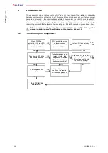
Page 32: ... follows Before carrying out diagnostics it is recommended to replace the battery with a charged one and ensure the efficiency of the starting keyswitch 9 1 Transmitting unit diagnostics When START is activated is the red LED lit steadily and does the buzzer sound STOP pushbutton or one of the movement actuators are activated disconnect it them Is the LED lit with a steady light Does the red LED b...

Page 33: ...dress keys E16SCHEU_ have been replaced do the following check that the transmitting unit is off and the receiving unit is powered switch on the transmitting unit press the START pushbutton without releasing it for at least 5 seconds Is the POWER ENABLE signal light switched off Is the connecting plug between the radio remote control and the machine connected correctly Correctly insert the connect...

Page 34: ...9 Diagnostics 30 LIMM SA0 00 fm ...

Page 35: ......

Page 36: ...Autec s r l Via Pomaroli 65 36030 Caldogno VI Italy tel 39 0444 901000 fax 39 0444 901011 www autecsafety com ...

Reviews: