


AUTEC - Air series
Operation
7
LIRPDE00-03
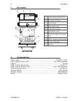
7 Operation
7.1
electronic module
The electronic module contains the address key, where the radio remote control configuration
data are also stored. The receiving unit cannot work without this address key.
7.2
DiP switches
DIP switch 1 is used to set the frequency band.
DIP switch 2 shall always be set in the OFF position: do not modify it.
7.3
Command outputs
The data sheet contains information regarding the correspondence between the commands
sent by the transmitting unit and the related output enabled in the receiving unit.
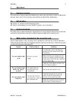
8
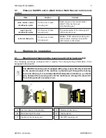
Malfunction signalled by the receiving unit
Use the light signals on the receiving unit to identify the radio remote control malfunction.
If the problem persists after the suggested solution has been carried out, contact the support
service of the machine manufacturer.
signals
Possible reason
solutions
The red indicator light
is off
Wrong or no power
supply.
Correctly plug in the connecting plug
between the radio remote control and
the machine.
Make sure that power supply wires are
correctly connected and that the power
supply value is within the limits specified
in the technical data.
Check the power supply protection fuse
and, if needed, replace it.
The red indicator light
blinks once every 5
seconds
The transmitting and
receiving unit do not
communicate.
Start up the radio remote control.
The red indicator light
blinks fast
The receiving unit does
not activate the outputs of
the commands sent.
Check that the outputs are correctly
wired and that the commands sent
activate the corresponding relays.
Check the protection fuse of the STOP
contacts and, if needed, replace it.
Summary of Contents for HACRP8
Page 8: ......


