


4
LIRPDE00-03
Technical data sheet
AUTEC - Air series
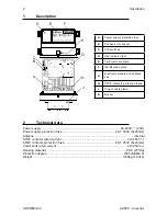
3
Technical data sheet
The technical data sheet contains the wiring diagram showing the connection between the
receiving unit and the machine. It also contains the transmitting unit configuration and shows
the matching between commands sent and machine functions/movements.
Each technical data sheet must be filled in, checked and signed by the installer, who is
responsible for a correct wiring.
A technical data sheet must always be kept toghether with this manual (always keep a copy
of the technical data sheet when it is used for administrative purposes).
The wiring of the receiving unit outputs must always reflect the wiring
indicated in the technical data sheet.
4 Plates
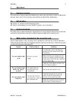
4.1
Plates on HACrP8 unit in a radio remote control
Plate
Position
Content
radio remote control
identification plate
On the cover of the
receiving unit.
Radio remote control serial number
(S/N), bar code and manufacturing year.
technical data plate
On the cover of the
receiving unit.
MODEL, TYPE and main receiving unit
technical data, marking and possible
radio remote control marks.
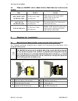
4.2
Plates on HACrP8 unit in a Take & release radio remote control
Plate
Position
Content
radio remote control
identification plate
On the cover of the
receiving unit.
Radio remote control serial number
(S/N), bar code and manufacturing year.
technical data plate
On the cover of the
receiving unit.
MODEL, TYPE and main receiving unit
technical data, marking and possible
radio remote control marks.
Summary of Contents for HACRP8
Page 8: ......


