background image

INSTALLATION OF A PRIORITY PAGING STATION

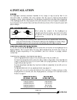
The following rules apply for connecting a paging station as a priority paging station to over 
ride all other paging stations:

The paging station must be enabled as a priority paging station (see Paging Station 
section on page 20).

The paging station that is used as a priority station must be connected to CAT5 RUN 1.

The only paging station that can be connected to CAT5 RUN 1 is the priority paging 
station. No other paging stations may share that CAT5 RUN.

CAT5 CABLE

CAT5 cable is the blue cable commonly used for data installations (other colours do exist). It 
consists of four twisted pairs of wires: this is why it is often referred to as UTP (Unshielded Twisted 
Pair). The most readily available cable uses solid conductors, like telephone wire. Cable with 
stranded conductors is available, and is more flexible.

CAT5 TERMINATION

Pre-wired CAT5 cable comes in two configuration standards, 568A and 568B. It is advisable to 
carry a good pre-wired cable for fault-finding. Both configurations will work with the 
DigiPageJr provided both ends have the same configuration. Be careful not to use a 
crossover cable which has one configuration at one end and the other configuration at the 
other end.

Ensure that the RJ45 connectors are suited to the cable used (solid or stranded) and that the 
correct crimp tool is used.

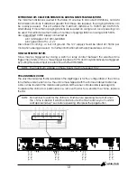
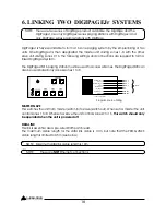
When wiring connectors, 568A standard wiring is recommended (see diagram). 

POWER REQUIREMENTS

The DigiPageJr can operate from the plug pack supplied and/or a separate 24V DC power 
supply.

NOTE: These 

are

NOT

 Ethernet connections.

NOTE: CAT5 cable consists of four pairs of wires: it is not sufficient to simply wire the two 

ends pin for pin, ignoring pairing.

12

A NOTE ABOUT GROUNDING:
It may be necessary in some circumstances to ground the DigiPageJr to eliminate 
noise in the system. This can be done using the negative terminal of the 24VDC IN 
euro connector or by making sure that the chassis is electrically connected to the 
equipment rack (which should be grounded).

White/Green 1

Green 2

White/Orange 3

Blue 4

White/Blue 5

Orange 6

White/Brown 7

Brown 8

568A configuration

CABLE

Shown with

locking clip

facing

Ground

Power

Ground

Busy-

Busy+

Priority

Data/Voice+

Data/Voice-

INSTALLATION SERIES

Australian Monitor

Summary of Contents for Digipage JR

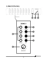
Page 1: ...2 PROG 2 PROG 2 PROG 2 PROG 3 PROG 3 PROG 3 PROG 3 PROG 3 PROG 3 PROG 3 PROG 3 PROG 4 PROG 4 PROG 4 PROG 4 PROG 4 PROG 4 PROG 4 PROG 4 MASTER 1 MASTER 2 MASTER 3 MASTER 4 MASTER 5 MASTER 6 MASTER 7 MASTER 8 TREBLE TREBLE TREBLE TREBLE TREBLE TREBLE TREBLE TREBLE BASS BASS BASS BASS BASS BASS BASS BASS PROG PROG PROG PROG PROG PROG PROG PROG MIC MIC MIC MIC MIC MIC MIC MIC 5 5 5 5 5 5 5 5 4 4 4 4 4...

Page 2: ...ation and main tenance servicing instructions in the literature To prevent electric shock do not use this polarized plug with an extension cord receptacle or other outlet unless the blades can be fully inserted to prevent blade ex To prevent electric shock match wide blade of plug to shock to persons accompanying the appliance posure wide slot fully insert Caution WARNING TO REDUCE THE RISK OF FIR...

Page 3: ... 5 3 Back Panel 8 4 Installation 11 5 Setup 14 6 Linking Two DigiPageJr Systems 16 7 Paging Station 18 8 Accessories 20 9 Troubleshooting Guide 20 10 Block Diagram 21 11 Dimensions 22 12 Specifications 23 INSTALLATION SERIES Australian Monitor 3 ...

Page 4: ... All Call There is also the ability to have one Paging Station as a priority paging station The Paging stations connect via an inexpensive and industry standard CAT5 cable network An overall priority input is also provided for emergency or evacuation signals The DigiPageJr is powered by an included external plug pack power supply or via 24VDC The DigiPageJr is a versatile and well featured product...

Page 5: ...OG 3 PROG 3 PROG 3 PROG 3 PROG 3 PROG 4 PROG 4 PROG 4 PROG 4 PROG 4 PROG 4 PROG 4 PROG 4 MASTER 1 MASTER 2 MASTER 3 MASTER 4 MASTER 5 MASTER 6 MASTER 7 MASTER 8 TREBLE TREBLE TREBLE TREBLE TREBLE TREBLE TREBLE TREBLE BASS BASS BASS BASS BASS BASS BASS BASS PROG PROG PROG PROG PROG PROG PROG PROG MIC MIC MIC MIC MIC MIC MIC MIC 5 5 5 5 5 5 5 5 4 4 4 4 4 4 4 4 3 3 3 3 3 3 3 3 2 2 2 2 2 2 2 2 1 1 1 1...

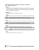
Page 6: ...puts may be mic or line see Back Panel on page 8 2 MASTER 1 8 This control adjusts the overall output level of the zone 3 TREBLE The treble control has 10dB of cut or boost at 10kHz The treble control affects the entire zone 4 BASS The bass control has 12dB of cut or boost at 100Hz The bass control affects the entire zone 5 PROG This control adjusts the overall level of the selected program source...

Page 7: ...ne is an area such as a function room that occasionally may need to be isolated from paging 8 ON This LED indicates there is power to the unit 9 POWER This switches power from the power supply included INSTALLATION SERIES Australian Monitor NOTE When 24VDC emergency power is supplied the unit is on regardless of the switch position NOTE When 24VDC emergency power is supplied this LED will always b...
Page 8: ......

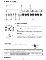
Page 9: ...able coming from the priority paging microphone station See Installation on page 12 for more information If you would like to have a paging station set as a priority over all other paging stations then it must be connected to this RJ45 socket and no other stations may use this connector or the run that it is on The paging station also needs to be set up as a priority station see Paging Station sec...

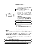
Page 10: ...in a Master Slave configuration see Linking Section on page 18 7 MASTER SLAVE This switch is used when linking 2 units in Master Slave configuration see Linking Section on page 18 8 POWER IN VAC This 2 1mm power socket accepts the 20VAC power supply provided with the unit NOTE Theseare NOT Ethernet connections NOTE Theseare NOT Ethernet connections 10 INSTALLATION SERIES Australian Monitor ...

Page 11: ...he installation the following rules apply Up to 4 Paging Stations may be connected to each of the four CAT5 runs Connections along the runs must be in a daisy chain configuration It is acceptable to create a short branch eg from a wall outlet to a paging station The maximum length of the branch is 10m The following table indicates the maximum distance allowable for a CAT5 run on a single port For ...

Page 12: ... will work with the DigiPageJr provided both ends have the same configuration Be careful not to use a crossover cable which has one configuration at one end and the other configuration at the other end Ensure that the RJ45 connectors are suited to the cable used solid or stranded and that the correct crimp tool is used When wiring connectors 568A standard wiring is recommended see diagram POWER RE...

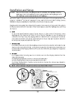
Page 13: ...gered by closing a switch or relay contact between the selected tone trigger input and common These trigger inputs are 5V TTL and may alternatively be triggered by pulling the desired input low referenced to the COMMON PRE ANNOUNCE CHIME The only internal setup that is available in the DigiPageJr is for the configuration of the chime tone that sounds in each zone The unit comes shipped with the ch...

Page 14: ...it is essential that you are starting from these initial settings Program Input Gain Controls half 12 o clock Master Volume off Mic level half 3 o clock Prog level half 3 o clock Step by step setup Confirm the initial settings of DigiPageJr Choose a zone that is conveniently located near to the DigiPageJr or further away if you feel you need the exercise This will be the referred to as TEST ZONE E...

Page 15: ... connected to DigipageJr prior to initiating the set up procedure 7 Balance the other program sources in the TEST ZONE rear panel PROG GAIN 8 Apply the front panel settings from TEST ZONE to all other zones 9 Using the front panel controls only set the individual zones to your preferred settings a Set balance between prog page b Set Eq c Set final master level 15 INSTALLATION SERIES Australian Mon...

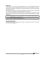
Page 16: ... slave the unit controls zones 9 to 16 This switch should only be operated when the unit is powered off DATA LINK This link is essential Use a pre wired CAT5 patch lead The maximum cable length for the data link cable is 10m but note that the PROG LINKS cable length is limited to 0 5m see below NOTE Theseare NOT Ethernet connections NOTE Maximum data link cable length is 10m Program Source Wiring ...

Page 17: ... as all 4 sources can be sent from the master to the slave via 1 CAT5 cable avoiding the need for Y cables The PROG TRIM on the slave unit operates independently of the master unit The PROG TRIM on the slave unit should be set to the same position as on the master Use a pre wired CAT5 patch lead The maximum cable length for the program source link cable is 0 5m However this cable should be kept as...

Page 18: ...n you are making a page or by another paging station Paging is not possible while the system is busy however zone selections can still be made Controls Introduction The Australian Monitor Installation Series DigiPageJrM8 and DigiPageJrM16 Paging Stations are 8 and 16 zone paging stations complete with a slimline gooseneck paging microphone The Paging stations are designed to be used with the DigiP...

Page 19: ...ur 7 TERMINATING In an RS485 network of which the DigiPageJr is part of it is important to terminate the last device in the network CAT5 RUN A jumper is provided for the data voice transmission to be terminated if that Paging Station is at the end of a CAT5 RUN see diagram Shipped as unterminated 8 PRIORITY If a Paging station is being used as a priority over all other Paging Stations then the fol...

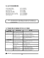
Page 20: ... up Incorrect system gain structure Lack of system ground Initailisation boot sequence Cable too long Cable fault Station lock up due to connection while system is live Emits high pitch whine Inconsistent operation LED s chase No response to controls Poor signal to noise ratio Cycle power on the DigiPageJr Check settings of all equipment Revisit Step by Step Setup Procedure Normal operation when p...

Page 21: ...REPEATED FOR PROGRAMS 2 4 MASTER SLAVE RS485 REC VOICE DATA PWM DECODER ROUTING LOGIC MICROPROCESSOR SUM INPUT LEVEL PAGE ENABLE CONTROL 20dB 13 5dB SIGNAL DETECT 0dB 36dB CHIME ALERT EVAC ZONE1 ZONE2 ZONE3 ZONE4 ZONE5 ZONE6 ZONE7 ZONE8 27dB PROGRAM SELECTION SWITCHES P1 P2 P3 P4 MECHANICALLY INTERLOCKING OFF 6 5dB PROG 6 5dB OFF 13 5dB 6 5dB internal TONE GEN OUTPUT CHIME ENABLE 1 OF 8 ZONES PAGE...

Page 22: ......

Page 23: ...ance 100kohm Sensitivity 150mV 14dBu Balanced XLR Input Impedance 1k3ohm Sensitivity 1mV 57dBu Min Trim 46dB Sum Input Input Sensitivity 160mV 13 5dBu Threshold 46dBu at output ind of input Frequency Response 15Hz 17kHz 0dB 3dB THD 0 005 Noise Page Mic 84dB Other Inputs 89dB All measurements are reference to 1 5V 6dBu 12 SPECIFICATIONS 23 INSTALLATION SERIES Australian Monitor ...

Page 24: ......

Reviews: