INSTALLATION SERIES
Australian Monitor
1
2
4
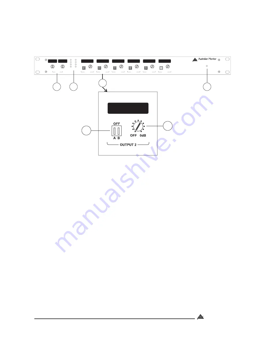
2. FRONT PANEL
5
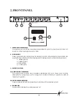
1. INPUT LEVEL CONTROL(S)
2. LEVEL METER
3. OUTPUT SECTION
3a. OUTPUT LEVEL CONTROLS
3b. INPUT ASSIGN SWITCHES
4. POWER LED
The input level controls are screwdriver adjustable trim pots. The input level controls can
boost or cut the input signal by up to 15dB.
These 4 segment LED meters show the strength of each of the AMIS26's input signals. LED
segments are calibrated to the following level markings and show the following colours:
-20dBu (green)
-10dBu (green)
0dBu (yellow)
+10dBu (red)
The output level controls are screwdriver adjustable trim pots. These level controls
attenuate the output level, with a range from -60dB at 'Minimum” position to 0dB at
“Maximum” position.
These recessed DIP switches assign input A and input B to a desired output.
This blue LED indicates the unit is powered “on”.
!
!
!
!
INPUT
ON
INSTALLATION SERIES
AMIS26
+10dB
-10dB
0dB
-20dB
0dB
0dB
-15dB
-15dB
+15dB
+15dB
A
B
OFF
OFF
OFF
OFF
OFF
OFF
0dB
0dB
0dB
0dB
0dB
0dB
OFF
OFF
OFF
OFF
OFF
OFF
A
A
A
A
A
A
B
B
B
B
B
B
OUTPUT 1
OUTPUT 2
OUTPUT 3
OUTPUT 4
OUTPUT 5
OUTPUT 6
A
B
3a
3b
Expanded view
3


