background image

www.austin-hughes.com

UM-IP-ATS-Q318V1 P.9

In


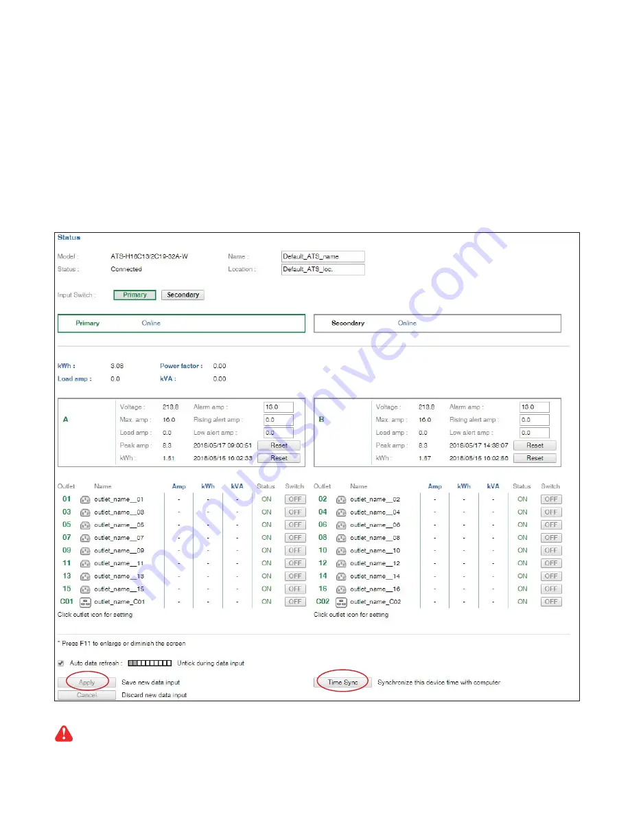
Status

 >,

-   View the installed ATS status
-   View aggregate current & energy consumption of the ATS
-   Select the preferred “ 

Input Switch

 “

-   Change “ 

Name

 “ & “ 

Location

 “ of ATS & Click “ 

Apply

 “

-   Change “ 

Alarm amp

 “ , “ 

Rising alert amp.

 “ & “ 

Low alert amp.

 “ of the ATS circuit & Click “ 

Apply

 “

    Default alarm amp. = 80% of circuit’s max. amp.
    Default rising alert amp. & low alert amp. = 0.0 ( disabled )
-   Click “ 

Reset

 “ to reset peak amp. or kWh of ATS’s circuit

-   Click “ 

Time Sync

 “ to update ATS’s real time clock from the computer logged in the ATS.

< 1.6 >   ATS-02-S GUI

Once ATS current loading is over the rated input current, input switching is NOT allowed  either by local 
or remote

Summary of Contents for ATS-02-S

Page 1: ...www austin hughes com UM IP ATS Q318V1 Inspired by Your Data Center User Manual Designed and manufactured by Austin Hughes ATS 02 S GUI SNMP for Intelligent ATS ...

Page 2: ...e personnel should open the chassis Opening it yourself could damage the equipment and invali date its warranty If any part of the equipment becomes damaged or stops functioning have it checked by qualified service personnel What the warranty does not cover Any product on which the serial number has been defaced modified or removed Damage deterioration or malfunction resulting from Accident misuse...

Page 3: ...es P 1 1 2 How to switch power input P 2 1 3 Hardware Specification P 3 1 4 ATS GUI ATS 02 S Key Features P 6 1 5 IP Configuration P 7 1 6 ATS 02 S GUI P 8 1 7 SNMP Setup P 11 1 8 ATS Firmware Upgrade P 15 1 9 DHCP Setting P 17 1 10 Command Line Interface CLI Access P 19 ...

Page 4: ... kWh Volt 3 62 228 0 7 8 9 5 4 3 2 1 67 8 C1 C2 Primary Secondary 1 2 3 5 4 1 8 color LCD 6 IP Port Input Preference Switch Power LED primary input Power LED secondary input Circuit Breaker 7 Primary Input attached with 3M cord inlet plug 8 Secondary Input attached with 3M cord inlet plug 9 Outlets ...

Page 5: ...input switch button on the front panel Set the input preference via WEBUI SNMP remotely Switch automatically when the preferred input source is powered off Once ATS current loading is over the rated input current input switching is not allowed either by local or remote However automatic switching is NOT affected ...

Page 6: ...g cord 2 x C14 C20 EN 60309 BS1363 CEE7 plug w 3M cord Outlet connectors C13 C13 C19 C19 IEC309 UK Schuko FR Local meter 1 8 color LCD Overload protection 1 x 10 amp circuit breaker for C14 inlet 1 x 13 amp circuit breaker for BS1363 inlet 1 x 16 amp circuit breaker for C20 EN16 60309 CEE7 inlet 1 x 20 amp circuit breaker for Open end 2 x 16 amp circuit breaker for EN32 60309 inlet Transfer time 1...

Page 7: ...inal Input frequency 50 60Hz Inlet plug cord 2 x L620 L630 plug w 3M cord Outlet connectors C13 C13 C19 C19 IEC309 Local meter 1 8 color LCD Overload protection 1 x 20 amp circuit breaker for L6 20P inlet 1 x 30 amp circuit breaker for L6 30P inlet Transfer time 10 16ms typical Electrical endurance 1 x 10⁵ operations Power consumption Approx 8VA Environmental Operating temperature 5 to 60 C degree...

Page 8: ... frequency 50 60Hz Inlet plug cord 2 x 515 L520 L530 plug w 3M cord Outlet connectors NEMA 5 20R Local meter 1 8 color LCD Overload protection 1 x 15 amp circuit breaker for NEMA 5 15P inlet 1 x 20 amp circuit breaker for NEMA L5 20P inlet 1 x 30 amp circuit breaker for NEMA L5 30P inlet Transfer time 10 16ms typical Electrical endurance 1 x 10⁵ operations Power consumption Approx 8VA Environmenta...

Page 9: ...y Features InfraPower ATS 02 S Features Capacity IP Dongle Group 1 ATS Number 1 Concurrent User 1 Features Input Source Selection Input Source Status Monitoring Energy Consumption kWh Monitoring Apparent Power kVA Monitoring Active Power kW Monitoring Power Factor Measurement Voltage Volt Monitoring Circuit Amp Monitoring Circuit Breaker Monitoring Amp Alarm R Alert L Alert Setting ...

Page 10: ... search the connected ATS Step 5 Enter device name in Name min 4 char max 16 char Default is Name Step 6 Enter device location in Location min 4 char max 16 char Default is Rack_001 Step 7 Enter password in Password for authentication min 8 char max 16 char Default is 00000000 Step 8 Enter new password in New password min 8 char max 16 char Step 9 Re enter new password in Confirm new password Step...

Page 11: ...r a TCP IP Ethernet network remotely Each web browser window supports only one ATS If you install more ATS multi windows will be required Step 1 Open Internet Explorer I E version 11 0 Step 2 Enter the configured ATS s IP address into the I E address bar Please refer to 1 4 IP configuration Step 3 Enter Login name Password Click Login Please refer to 1 4 IP configuration ...

Page 12: ...p Rising alert amp Low alert amp of the ATS circuit Click Apply Default alarm amp 80 of circuit s max amp Default rising alert amp low alert amp 0 0 disabled Click Reset to reset peak amp or kWh of ATS s circuit Click Time Sync to update ATS s real time clock from the computer logged in the ATS 1 6 ATS 02 S GUI Once ATS current loading is over the rated input current input switching is NOT allowed...

Page 13: ...ake changes effective In Outlet Setting In System Change the outlet name Click Apply to make the change effective Change the ATS name location Change the IP address subnet mask gateway For static IP setting only Select ON in DHCP to enable DHCP setting Tick Force HTTPS to provide data transmission security Click Apply to make the changes effective 1 6 ATS 02 S GUI ...

Page 14: ...es com resources software infrapower Step 2 Select the MIB file of the intelligent ATS II Enabling SNMP Support i The following steps summarize how to enable the ATS for SNMP v1 v2 support Step 1 Connect the ATS to a computer Please refer to 1 4 IP configuration Step 2 Open the Internet Explorer I E version 11 0 Step 3 Enter the configured ATS s address into the I E address bar Default IP address ...

Page 15: ... Step 9 Input SNMP port Default is 161 Step 10 Input Read Community Default is public Step 11 Input Write Community Default is private Step 12 Click Activate in Station 1 to enable the trap service Step 13 Input Trap Station IP Trap Port Trap Community of Station 1 Step 14 Repeat Step 12 13 for Station 2 3 Step 15 Click Apply to finish the SNMP v1 v2 settings ...

Page 16: ... SNMP v3 support Step 1 Connect the ATS to a computer Please refer to 1 4 IP configuration Step 2 Open the Internet Explorer I E version 11 0 Step 3 Enter the configured ATS s IP address into the I E address bar Default IP address is 192 168 0 1 Step 4 Enter Login name Password Default login name password are 00000000 Step 5 Select SNMP from the left navigation pane ...

Page 17: ...er Default is usm_user1 Step 13 Select None MD5 SHA in Auth algorithm If you select Read Write in User role you MUST select MD5 SHA in Auth algorithm Step 14 Input the Auth password Default is 00000000 Step 15 Select None DES AES in Privacy algorithm If the Auth algorithm is NONE NO privacy algorithm can be selected Step 16 Input the Privacy password Step 17 If you want to receive trap message sel...

Page 18: ...www austin hughes com downloads IPDL IPDfirmware html Step 2 Select the firmware file for intelligent ATS Step 3 Connect the intelligent ATS to the computer Please refer to 1 4 IP configuration Step 4 Open the Internet Explorer I E version 11 0 Step 5 Enter the configured ATS s IP address into the I E address bar Default IP address is 192 168 0 1 Step 6 Enter Login name Password Default login name...

Page 19: ...xxx img from the specific path in the pop up window and Click Open Step 10 Click Upgrade to start the upgrade process It takes a few minutes to complete DO NOT close the web browser or refresh the web page during the upgrade process Step 11 Once complete the login page will display again If the login page does not display open a new tab and try to access the login page ...

Page 20: ...p 2 Open the Internet Explorer I E version 11 0 Step 3 Enter the default IP address of the Intelligent ATS into the I E address bar Default IP address is 192 168 0 1 Step 4 Enter the Login name Password Default login name password are 00000000 Step 5 Select System from the left navigation pane Step 6 Select ON from DHCP click Apply to save the settings ...

Page 21: ...es com UM IP ATS Q318V1 P 18 1 9 DHCP Setting Step 7 Select Firmware from the left navigation pane Step 8 Record the Device MAC address Step 9 Assign an IP address to the Intelligent ATS from your DHCP server Complete ...

Page 22: ... login name password are 00000000 You can change the following settings via CLI access i System settings Change temperature display unit change the temp unit to be displayed in the WEBUI Change system RTC date time set the system time of the ATS Change network settings change the IP settings of the ATS Change features services a Enable disable management software support b Enable disable SNMP agen...

Page 23: ...www austin hughes com UM IP ATS Q318V1 P 20 ...

Page 24: ...ify product specifications without prior notice and assumes no responsibility for any error which may appear in this publication All brand names logo and registered trademarks are properties of their respective owners Copyright 2018 Austin Hughes Electronics Ltd All rights reserved ...

Reviews: