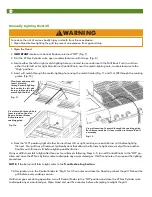
background image

12

D

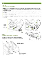
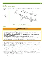
Step 14

Side Burner Igniter Wire Connection

The Side Burner Igniter Wire is pre-installed and connected to 
the Ignition Box. Attach the wire to the Side Burner electrode by 
sliding the wire connector onto the electrode terminal.

Underside view of 

Side Table/Side Burner

Note:

Shown without Regulator 

Hose for clarity.

Valve

A

5/32 x .31” Bolt

2 pc

B

Venturi 

Windscreen

Side Burner 

Bracket

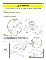
Step 13

Side Burner Valve Assembly

NOTE:

 Side Burner Valve is already attached to the regulator hose. Hose is not shown in some illustrations for clarity.

A.

 Install the Side Burner Valve from underneath the LEFT Side Table. Remove the screws from the side burner bracket 

and set aside with bracket.

B. 

Tilt venturi end of burner down and slide rectangular venturi windscreen toward back of grill to expose open end of 

burner tube.

C. 

Insert the valve stem out through the hole in the bezel and fascia on the front of the side table. Next insert the 

nozzle into the opening in the burner tube. 

D.

 Attach the valve to the front of the side table by installing two 5/32” x .31” Bolts through the Control Knob Bezel and 

front of the Side Table into the threaded Valve bracket holes. Slide the windscreen back into position and replace the side 
burner bracket.

C

Summary of Contents for Vantage 68R5A9SSS1

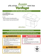
Page 1: ...t with the user SAVE THESE INSTRUCTIONS If you smell gas 1 Shut off gas to the appliance 2 Extinguish any open flame 3 Open lid 4 If odor continues keep away from the appli ance and immediately call your gas supplier or your fire department WARNING DANGER LP Gas Grill Assembly and Use Manual 68R5A9SSS1 Do not store or use gasoline or other flammable vapors and liquids in the vicinity of this or an...

Page 2: ... fire or explosion Never use alcohol prescription or non prescription drugs while assembling or safely operating this appliance Do not connect LP Gas Cylinder until assembly is complete except as noted for first time use leak test as de tailed on pages 19 20 WARNING To reduce the risk of a laceration hazard wear protective gloves when handling parts that have sharp edges To reduce the risk of bodi...

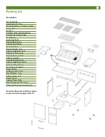
Page 3: ...ont Crossbar Drawer Tracks 2 pcs Cabinet Side Panel Left Back Panel Brace wire Cylinder Retainer Bolt Cabinet Upright Cylinder Blocking Wire Cabinet Side Panel Right Cabinet Bottom Panel Front Corner Brackets Drawer Body Locking Caster 2 pcs Fixed Casters 2 pcs Cabinet Door Left Drawer Front Cabinet Door Right Door Drawer handle 3 pcs Hardware Package not pictured Detailed Parts List and Illustrat...

Page 4: ...e 25 Manually Lighting the Side Burner 26 Manually Lighting the Rotisserie Burner 26 Cooking on the Gas Grill Grill Cooking Direct Method 27 Roasting Indirect Method 28 Rotisserie Cooking 29 Warming Rack 30 End of Cooking Session 30 Care and Maintenance Cleaning the Grill 31 How to Clean the Burners 32 Emergencies 34 Troubleshooting 34 Important Notice LP Cylinder with OPD 36 Parts List 38 Parts I...

Page 5: ... 20 x 60 Bolts through the caster bracket holes into the threaded holes in the Cabinet Bottom Panel Tighten the bolts Push the lever on the two Locking Casters to lock so the caster wheels do not roll Step 2 Cabinet Bottom Assembly With Back Panel on floor place Cabinet Bottom Panel against Back Panel edge and align the holes Install three 1 4 20 x 50 Bolts through the holes and secure with three ...

Page 6: ...nel and Right Side Panel to Cabinet Bottom Panel with six 1 4 20 x 50 Bolts and 1 4 20 Nuts Secure Left and Right Side Panels to Back Panel with four 5 32 x 31 Bolts through the inside of the Back Panel 1 4 20 x 50 Bolt set 6 pc 5 32 x 31 Bolt set 4 pc ...

Page 7: ...de Panels with eight 1 4 20 x 5 bolts Flat side of Bracket should be to front of cabinet so it is flush with front edges Step 4 Front Crossbar Assembly Turn cart assembly up on casters Attach Front Crossbar with the triangle braces facing down and the flat surface to the front to Side Panels with six 1 4 20 x 50 Bolts into the threaded holes in the top inside ends of Side Panels front crossbar 5 3...

Page 8: ...ch to Bottom Panel with one 5 32 x 47 Bolt To reduce the risk of serious bodily injury or death from fire or explosion Never remove guards or devices to prevent storage of spare or oversize LP Gas Cylinders not recommended for this grill WARNING Step 7 Door Handle Assembly Assemble Handle to Left Door using two 5 32 x 31 Bolts Repeat with Right Door Note 2 extra screws provided 5 32 x 31 Bolt set ...

Page 9: ...es in inside of Drawer Front B A Step 8 Model 6805 6804 with drawer Drawer Track Assembly and Cylinder Retaining Bolt Installation A Attach one Drawer Track to Back Panel and Cabinet Upright using four 5 32 x 31 Bolts Attach other Drawer Track to Back Panel and Right Side Panel using four 5 32 x 31 Bolts B Install the Cylinder Retainer Bolt through the hole in the back of the Bottom Shelf into the...

Page 10: ...g assembly steps s 11 and 12 will require two people CAUTION Step 11 Hood Body To Cart Assembly Lift the Hood Body Assembly over the cart assembly and set it down until it rests on the inside top flanges of the cart Align the holes in the side of the Hood Body with the holes in the Side Panel brackets Insert four 1 4 20 x 50 Bolts through the holes in cabinet flanges and into threaded inserts in f...

Page 11: ...olts all the way Leave 1 8 of each Bolt exposed Align the bottom two holes keyhole slots in detail on the inner side of the LEFT Side Table with the two bolts thread ed partly into the inserts in the Side of the Bowl then slide the Side Burner Table over the Bolts B Holding the Side Burner Table in place install two 1 4 20 x 50 Bolts from the inside of the Bowl into the two top threaded holes in t...

Page 12: ...illustrations for clarity A Install the Side Burner Valve from underneath the LEFT Side Table Remove the screws from the side burner bracket and set aside with bracket B Tilt venturi end of burner down and slide rectangular venturi windscreen toward back of grill to expose open end of burner tube C Insert the valve stem out through the hole in the bezel and fascia on the front of the side table Ne...

Page 13: ...uded ends to fall into the three holes around the Side Burner B A To avoid possible damage to grill DO NOT ATTEMPT TO LIFT GRILL BY THE SIDE TABLES CAUTION Step 16 A Bottom Body Panel Assembly Slide the Bottom Body Panel into the guides of the Body assembly Secure Bottom Body Panel to Body assembly with one 5 32 x 31 Bolt on each side B Foil Pan Grease Pan Assembly Insert the Foil Pan into the Gre...

Page 14: ...x Seat securely Step 18 Flavor Activator Cooking Grid Assembly A Lay a large Flavor Activator over each Tube Burner on the lower body ridges Lay a small Flavor Activator between each large Flavor Activator Each Flavor Activator has individual guides on the lower body ridges to keep in place B Place the Cooking Grids over the Flavor Activators on the upper Body ridges Large Flavor Activator cooking...

Page 15: ...dingly Never store a spare LP Gas Cylinder under or near the LP gas grill Always turn off the LP Gas Cylinder at the LP Gas Cylinder valve when the gas grill is not in use WARNING 1 Disconnect LP Gas Cylinder from grill and store outside in a dry well ventilated area away from any sources of heat or ignition Re cap LP Gas Cylinder valve with the Safety Cap 2 Remove Burners and wrap with aluminum f...

Page 16: ...age corrosion leakage exces sive rust or other forms of visual external damage it may be hazardous and should be checked by a liquid propane supplier Do not use an LP Gas Cylinder with a damaged valve Do not store a spare LP Gas Cylinder under or near the LP gas grill When grill is not in use turn off all grill Control Knobs LP Gas Cylinder valve and disconnect LP Gas Cylinder Never fill the LP Ga...

Page 17: ...ill be necessary You will be asked to forward your proof of purchase via e mail or to fax your proof of purchase to 423 639 1055 and reference your model and serial number It is important to register your grill and retain your receipt Connecting LP Gas Cylinder 1 Fill empty OPD LP Gas Cylinder at your local gas supplier 2 Place the LP Gas Cylinder in the large hole in the Bottom Panel inside the c...

Page 18: ...le and flammable material Locate your LP gas grill at least 10 feet away from your house or any building Maintain minimum clearances of 36 from back and sides of grill to any combustible construction Do not locate this appliance under overhead unprotected combustible construction This outdoor cooking appliance is not intended to be used in or on boats or installed in or on recreational ve hicles N...

Page 19: ...aching the Side Tables and illustrate the initial steps in the FIRST TIME USE LEAK TEST Detach the Control Panel from the Grill Body Firebox by removing the two 5 32 Bolts from each end Fig 1 Gently pull the Control Panel away from the Body until Valves disengage from the Tubular burner ends Fig 2 Support the Control Panel to keep tension off of the igniter wire leads or detach the wire leads from...

Page 20: ...not to over bend or kink the corrugated rotisserie gas line If all valve ends do not immediately align with the burner end openings starting at one end grasp the tube burner inside the firebox and gently move it until the valve seats in the open end Also note that the end caps of the control panel skin fit to the outside of the flanges on the firebox as shown in Figure 4a Fig 4a Fig 4 corrugated r...

Page 21: ...g coupling nut on regulator in a counterclockwise direction until regulator is released from threaded LP Gas Cylinder nozzle 10 Place the protective cap over LP Gas Cylinder nozzle 11 Re attach the wire leads to the Igniter Button Replace Control Panel around flanges at Bowl ends and align bolt holes on each side Replace and retighten all bolts Fig 1 Should you notice that your Burner s are gettin...

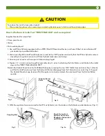
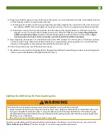
Page 22: ...linder valve counterclockwise 4 Push far left Main Burner Control Knob in on Control Panel and turn counterclockwise to the High position Figs 7 and 9 To reduce the risk of serious bodily injury or death from fire or explosion Open Hood before lighting the grill to prevent an explosion from gas build up During failed lighting attempts or if the Burners go out during operation turn Control Knobs Of...

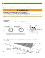
Page 23: ...e minutes then repeat the lighting procedures Lighting the Rotisserie Burner Model 6805 NOTE Do not operate the Sear burner and Rotisserie burner at the same time Do not use the Rotisserie burner when main burners are in use Remove the Warming Rack when using the Rotisserie Burner to prevent damage to the Warm ing Rack 1 Open lid during lighting 2 Make sure the Rotisserie burner knob is in the Off...

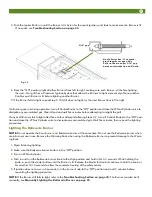
Page 24: ...other Confirm each Burner is lit before lighting another Burner If any or all Burners fail to light after three or four attempts following Steps 3 5 turn all Control Knobs to the Off po sition and close the LP Gas Cylinder valve to dissipate any accumulated gas Wait five minutes then repeat the lighting procedures NOTE If the Burner still fails to light refer to the Troubleshooting Section 7 After...

Page 25: ...e or four attempts following Steps 3 6 turn the Side Burner Control Knob to the Off position and close the LP Gas Cylinder valve to dissipate any accumulated gas Wait five minutes then repeat the lighting procedures NOTE If the Burners still fail to light refer to Troubleshooting Section The Burner can be lit manually see Manually Lighting the Side Burner Check The Flame The Burners have been pres...

Page 26: ...fore lighting the grill to prevent an explosion from gas build up When manually lighting Side Burner use Match light Holder WARNING Hold lit match near Burner Fig 14 Manually Lighting the Rotisserie Burner Model 6805 NOTE Do not operate the Sear burner and Rotisserie burner at the same time Do not use the Rotisserie burner when main burners are in use Remove the Warming Rack when using the Rotisse...

Page 27: ... for build up Empty excess grease to avoid a grease fire in the pan If you notice grease or other hot material dripping from the grill onto the valve hose or regulator turn off the gas supply immediately After the grill has cooled determine the cause and correct it After cleaning the valve hose and regulator assembly perform a leak test before continuing use See Performing a Leak Test Do not opera...

Page 28: ...the heat source The Burners heat up the Flavor Activators under the Cooking Grids which in turn heat the food on the grill The natural food juices from cooking fall onto the hot Flavor Activators below and vaporize Rising smoke bastes the food giving it that unique barbecued flavor Use the Direct Cooking method for foods that take less than 25 minutes to cook steaks chops kabobs sausages and more ...

Page 29: ...king mechanism to allow the counterweight to turn freely Set the rotisserie rod in the slots of the rotisserie brackets Let the heaviest side of the meat rotate to the bottom Adjust the counterweight to the side opposite the heaviest side of the meat up Tighten the counterweight in place Periodically check to see if the meat turns smoothly while cooking Adjust the counterweight as necessary Use a ...

Page 30: ...Allow grill and the grease in the Foil Pan to completely cool before emptying handling parts cleaning moving or storage Empty the Foil Pan and Grease Pan after each cooking session so excessive grease does not accumulate Never light the LP gas grill without the Foil Pan Grease Pan and Bottom Panel in place WARNING 1 After each cooking session close the Hood and turn the Burners to the High positio...

Page 31: ...For further cleaning use hot soapy water and a cloth or nylon bristled brush only Do not immerse the Gas Controls or Manifold in water Avoid getting water in the Burner holes Burners Burning off the residue after cooking will keep the Burners clean with normal usage provided the Burners are op erating correctly Clean the Burners annually or whenever heavy build up is found to ensure that there are...

Page 32: ...ck wall of bowl Gently lift the rear of the Burner Fig 17 Slide the Burner towards the grill back to move the Venturi Hole off of the Valve nozzle Fig 18 Lift each Main Burner from the grill In order to prevent flashbacks the Burner s should be removed from the grill and cleaned periodically especially if the grill has been stored for an extended period of time Burner Venturi Tube Valve Control Kn...

Page 33: ...of the Burner Fig 18 Replace the Bolts and Nuts that fasten the Burner Flange to Back Wall 9 If the grill is to be stored wrap Burners in a protective cover to keep insects out 10 Check Burner operation after re assembly 11 Replace Flavor Activators and Cooking Grids NOTE The IR sear burner and IR rotisserie burner do not require manual cleaning Do not scrape the ceramic with any sort of tool Remo...

Page 34: ...r s and inspect for blockage from spider webs insect nests or rust See How to Clean Burners section Replace any damaged parts Turn off Control Knobs and LP Gas Cylinder valve Once fire is out and grill has cooled off Clean residual food particles and excess grease from inside firebox area grease cup and other surfaces If you can safely reach the Control Panel turn Control Knobs to Off then close t...

Page 35: ...light grill Clean the Burners See How to Clean Burners in Care and Maintenance Dry Electrode with clean cloth Air dry or use blow dryer Reconnect the wire Replace Igniter Wire Electrode assembly Call the Customer Service Department Follow lighting procedure but hold control knob IN for at least 10 seconds Blow or drain water out of ceramic center and or body of burner Close lid when not in use See...

Page 36: ...ts and nuts 1 Loosen bolts and bottom door brackets Align doors 2 Loosen bottom side panel bolts inside cabinet Apply pressure to one side until doors are aligned Retighten bolts Turn front of grill away from wind or increase flame height Check LP Gas Cylinder Refill if necessary See Low flame problem above If your problem is not resolved from the information provided above please call Customer Se...

Page 37: ...37 ...
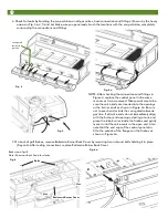
Page 38: ...mper 2 25 Hood 1 26 Warming Rack 1 27 Main Cooking Grid 3 28 Small Flavor Activator 3 28A Large Flavor Activator 4 29 Rotisserie Burner 1 30 Sear Burner 1 31 Right Side Table 1 32 Main Electrode Assembly 2 33 Tool Hooks 3 34 Bottom Body Panel 1 35 Foil Pan 1 36 Grease Pan 1 37 Cabinet Back Panel 1 38 Drawer Tracks 2 39 Cylinder Blocking Wire 1 40 Cabinet Side Panel RIGHT 1 41 Match Holder Chain 1 ...

Page 39: ...net If you need a replacement part under warranty a proof of purchase will be necessary You will be asked to forward your proof of purchase via e mail or to fax your proof of purchase to 423 639 1055 and reference your model and serial number It is im portant to register your grill and retain your receipt Caution If it is necessary to replace thermocouple safety sensors Key 55 or 56 use only Meco ...

Page 40: ...he option of MECO CORPORATION without charge This warranty does not include the cost of any inconvenience or property damage due to failure of the product and does not cover damage due to misuse abuse accident damage arising out of transportation of the product damage incurred through commercial use or failure to perform normal and routine maintenance LIABILITY FOR CONSEQUENTIAL PROPERTY OR COMMER...

Reviews: