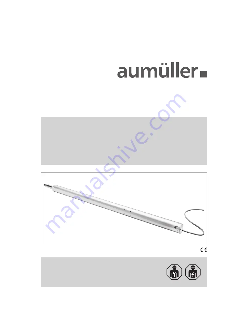
PLS S12 24V DC S
PINDLE
D
RIVE
FOR
WINDOWS
according to Machinery Directive 2006 / 42 / EC (annex VI)
Assembly and Commissioning
Instructions
Page 1: ...PLS S12 24V DC SPINDLE DRIVE FOR WINDOWS according to Machinery Directive 2006 42 EC annex VI Assembly and Commissioning Instructions...
Page 2: ...NSTALLATION STEP 4A B Hole layout for frame bracket and casement bracket Activation on HSK NSK INSTALLATION STEP 4C Sky light Activation on HSK INSTALLATION STEP 5A Assembly for direct operation Activ...
Page 3: ...re to comply with the warning notes can re sult in minor or moderate reversible injuries Failure to comply with the warning notes can lead to damage to property WARNING AND SAFETY SYMBOLS IN THESE IN...
Page 4: ...plication as NSHEV natural smoke and heat exhaust ventilator s for ventilation without dual purpose for ventilation in accordance with EN12101 2 The need for a risk assessment at the installation site...
Page 5: ...ontact based anti trap protection 20 ZAA 8 2 Pressure sensitive safety switch strips or Motor current monitoring systems internal and external Hold to run switch stops movement at HSK 20 mm at a closi...
Page 6: ...ent the electrical supply data see machine plate and performance limits see technical data as well as the mounting and installation instructions of the drive must be strictly observed and adhered to D...
Page 7: ...ring cables Specimen Guideline on Conduits German designation MLAR The types of cable cable lengths and cross sections shall be selected in accordance with the manufacturer s technical data If necessa...
Page 8: ...al conditions Operation Ambient temperature 5 C 60 C Relative humidity 90 less 20 C 50 less 40 C no formation of condensation Observe temperature range during installation Transport Storage Storage te...
Page 9: ...cting cable non halogen grey 3 x 1 0 mm 3 m v Speed 16 0 mm s 16 0 mm s s Stroke 300 1200 mm L Length s 465 mm see order data Sound pressure level 70 dB A Application natural ventilation SHEV ferralux...
Page 10: ...tube end with interior thread M12 1 515063 Drive housing painted powder coated in other RAL colours Lump sum for coating 516030 Specify at order stage 1 20 516004 21 50 516004 51 100 516004 up 101 516...
Page 11: ...1200 Schub Push FH Pullout force 25000 N fastening depended Spindle tube Stainless steel Connecting cable non halogen grey 3 x 1 0 mm 3 m v Speed 7 8 mm s 7 8 mm s s Stroke 300 1200 mm L Length s 465...
Page 12: ...tube end with interior thread M12 1 515063 Drive housing painted powder coated in other RAL colours Lump sum for coating 516030 Specify at order stage 1 20 516004 21 50 516004 51 100 516004 up 101 516...
Page 13: ...N fastening depended Spindle tube Stainless steel Connecting cable non halogen grey 3 x 1 0 mm 3 m v Speed 4 0 mm s 4 0 mm s s Stroke 200 750 mm L Length s 600 mm see order data Sound pressure level...
Page 14: ...5063 Drive housing painted powder coated in other RAL colours Lump sum for coating 516030 Specify at order stage 1 20 516004 21 50 516004 51 100 516004 up 101 516004 Extra length connecting cable 5 m...
Page 15: ...dow total weight casement including snow load PLS15 max 270 kg PLS30 max 550 kg PLS50 max 900 kg 1200 mm solo 2500 mm tandem 2500 mm FAB max FAH max HSK AREAS OF APPLICATION AND CASEMENT SIZES Top hun...
Page 16: ...l nge 1000 mm Abstand Antrieb Band Band BD Antrieb A Planning the opening angle for direct operation This planning diagram is a general guide to help establish the most appropriate drive stroke for th...
Page 17: ...arranty claim expires Predictable misuse It is imperative that foreseeable misuse of drives is avoided Here are a few examples do not connect 24 V DC drives to a 230 V AC mains voltage observe synchro...
Page 18: ...y and health of persons 1 The design of the drive must fulfill the requirements 2 The fastening accessories casement brackets or frame brackets must fit the window profile the profile dependent hole l...
Page 19: ...K82 1 Suspension 8 mm Mounting with K121 1 Casement bracket F36 Casement bracket F40 Support B2 Suspension 8 mm Mounting with K121 1 Suspension with bore 8 mm Mounting with casement bracket F 40 20 46...
Page 20: ...spension Collar screw B9 Clevis B28ST Eye bolt B29ST for adjustable clamping B6 with M10 thread with M12 thread 8 20 10 1 2 M 40 HSK NSK NSK HSK NSK 50 3 40 14 80 DIN 912 M6x25 For K70 K82 1 K121 K121...
Page 21: ...g System SCH CO AWS 57RO Roof window outward opening Frame assembly HSK Top view Drilling HSK INSTALLATION STEP 4A HOLE LAYOUT ACTIVATION ON HSK 05 HOLE LAYOUT ACTIVATION ON HSK 23 15 15 9 5 20 20 5 1...
Page 22: ...indow outward opening Frame assembly HSK Top view Drilling HSK HOLE LAYOUT ACTIVATION ON HSK A Top view 05 HOLE LAYOUT ACTIVATION ON HSK F28 1 K82 1 B6 20 20 15 5 35 35 50 50 30 9 5 15 13 5 mm Ausfr s...
Page 23: ...stem WICONA Wictec 50 Roof window outward opening Frame assembly NSK Top view Drilling NSK 20 20 5 15 35 35 50 50 13 5 mm Ausfr sung 130 mm Ausfr sung 20 20 70 70 110 55 30 30 30 30 60 60 19 16 05 INS...
Page 24: ...ACTIVATION ON NSK Sky light system Eternit Fumilux4000 Sky light Frame assembly HSK Sky light Frame assembly solo Sky light Frame assembly tandem HSK INSTALLATION STEP 4C SKY LIGHT 60 60 30 30 21 5 21...
Page 25: ...project specific documents and drawings INSTALLATION STEP 5A L O C T I T E Make sure they are parallel to casement edge Fit frame bracket K82 1 Secure fasteners against loosening i e by applying remo...
Page 26: ...sure Tighten the cylinder head screw M6 from the adjustable clamping B6 to torque of 10Nm Drehmoment Attach drive with adjustable clamping B6 to frame bracket K82 1 Screw in the collar screw and tight...
Page 27: ...cking compound such as Loctite Carefully clear away drilling swarfs to prevent seals from being damaged Avoid surface scratches for example by using masking tape Determine fastenings Produce drill hol...
Page 28: ...ad out the cotter pin Fett 2 1 7 6 1 7 5 F11ST F11 VA 14 G1 8 K127 1 RA RA FL FL A Screw M6 middle position facilitates location of drive in the adjustable clamping B6 Remove this screw after assembly...
Page 29: ...unting bracket so that their axes are in line Check contact pressure of case ment To fit the second drive A A Window must be fully closed Adjust casement pressure Tighten the cylinder head screw M6 fr...
Page 30: ...AK Master Slave 1 BU AK Slave 2 Slave 3 Umpolung junction box site supplied Connection no synchronous running if not connected S12 NSK HSK INSTALLATION STEP 6 ELECTRIC CONNETCTION Connection assignmen...
Page 31: ...ber Application Rated voltage Parameterizable drives Scope of delivery 524178 Hard and software for configuration of drives supplied by Aum ller Aumatic GmbH 24V DC 20 24V DC type S3 S12 S12 V 2 230V...
Page 32: ...aded from the homepage of Firm AUM LLER AUMATIC GmbH www aumueller gmbh de SAFETY CHECK AND TEST RUN Formula to calculate the required wire cross section of a supply line Calculation example Available...
Page 33: ...per formed The drive itself is maintenance free Defect devices may only be repaired in our factory Only replacement parts of the manufacturer may be used When the connection cable of this device is da...
Page 34: ...rmal use The warranty period for delivered material is twelve months Warranty and liability claims for personal injuries or material damages are excluded if caused by one or more of the following No p...
Page 35: ...General Terms and Conditions of AUM LLER AUTOMATIC GmbH apply to all offers supplies and services The publication of these assembly and commissioning instructions supersedes all previous editions CERT...
Page 36: ...n Tel 49 8271 8185 0 Fax 49 8271 8185 250 info aumueller gmbh de 9000017000_V0 1_KW05 14 www aumueller gmbh de AUM LLER AUMATIC GMBH Gemeindewald 11 86672 Thierhaupten Tel 49 8271 8185 0 Fax 49 8271 8...