21.
Electronic positioner (option)
21.1 Technical data
21.2 Setting
The positioner in the actuator controls AUMA MATIC is programmed
according to the purchase order details and is set together with the actuator
prior to delivery.
Due to peculiarities of the regulating system not known beforehand, a read-
justment may become necessary. Before adjusting the positioner, the pro-
gramming of the positioner should be checked.
.
Check programming of the logic board according to subclause 20.2.
The self-retaining REMOTE function (see table 4) must be
switched off in conjunction with the positioner.
.
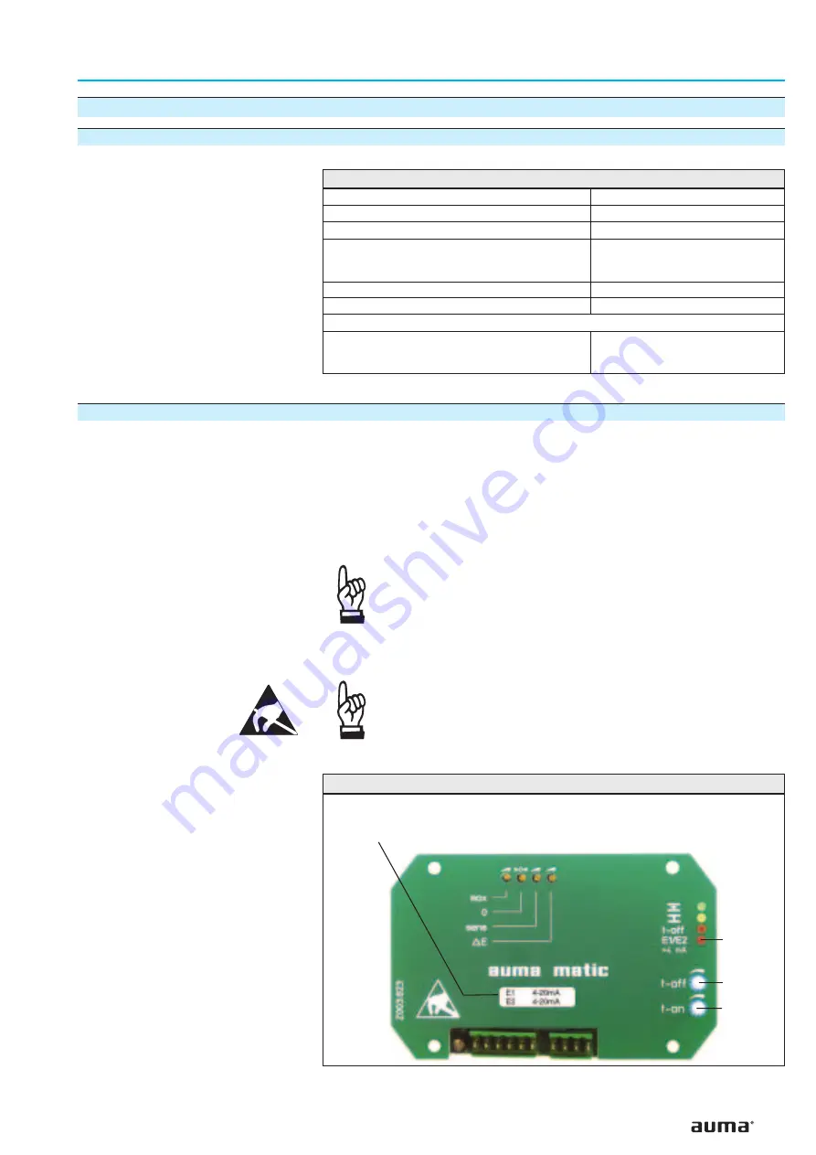
Take off cover plate (figure 47) and carry out required programming at
positioner board (figure 48) according to tables 6 and 7.
Prior to setting, it must be ensured that the circuit for the
position feedback E2 (see wiring diagram) is closed
(measuring device or link). In case of missing signal E2, the
LED (V10) “E1/E2 < 4 mA” (figure 47) is illuminated and the
positioner shows no reaction.
35
Multi-turn actuators SA 07.1 – SA 30.1/SAR 07.1 – SAR 30.1
Operation instructions
with actuator controls AUMA MATIC AM 01.1/AM 02.1
Command signal (input signal E1, set value)
0/4 – 20 mA (option: 0 – 5 V)
Feedback (input signal E2, actual value)
0/4 – 20 mA (option: 0 – 5 V)
Sensitivity (dead band)
Δ
E (P9)
0.5 % – 2.5 %
Fine tuning “Sens” (P7)
(useful for output speeds < 16 rpm only;
not possible for 1-ph AC motors)
min. 0.25 %
Pause time “t-off ”(P10)
0.5 – 10 s
Input resistance
250 Ohm
Modulating duty with stepping mode
(not required for modulating setting)
:
Running time “t-on” (P8)
effective until error is
£
25 %; then set value is
automatically reduced by 3.
0.5 – 15 s
Table 5: Technical data for positioner
Figure 47: Cover plate positioner - standard
V10 (red)
P10
P8
Label with signal indication
(in our example: E1 = 4 – 20 mA, E2 = 4 – 20 mA)


