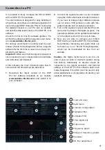
Audiotec Fischer HELIX DSP.2 Manual Download Page 15

15

1

  Line Input

6-channel  pre-amplifier  input  to  connect   signal 

sourc es  such  as  radios.  Input  sensitivity  is 

 factory-set to 4 Volts (maximum CCW position). It 

is  possible  to  vary  the  sensitivity  between  2  and 

4 Volts.  

2

  Clipping LED

This LED lights up red if one of the six 

Line Inputs 

or 

Highlevel Inputs

 is overdriven. The LED has no 

function if the device is fed with digital input signals. 

If this LED lights up reduce the input sensitivity by 

using the control 3 (

Input Sensitivity

) until the LED 

goes out.  

3

  Input Sensitivity

This control is used to adapt the input sensitivity of 

the low- and highlevel inputs to the output voltage 

of the connected signal source. This is not a volume 

control, it´s only for adjusting the signal processors 

gain. The control range of the RCA / 

Line Input

 is 

2 - 4 Volts and 3.5 - 11 Volts for the 

Highlevel Input

Attention:

 It is mandatory to properly adapt the in-

put sensitivity of the DSP.2 to the signal source in 

order to avoid damage to the signal processor. 

If the 

Highlevel Input

 is used in combination with a 

standard car radio we recommend an input sensitiv

-

ity  of  roughly  9 Volts.  For  this  purpose,  turn  the 

 control from max. CCW position to 8 o’clock posi

-

tion.   

4

  Highlevel Input

6-channel  highlevel  loudspeaker  input  to  connect 

the signal processor directly to loudspeaker outputs 

of OEM / aftermarket radios or OEM amplifiers that 

do not have any pre-amplifier outputs. Input sensi

-

tivity is factory-set to 11 Volts (maximum CCW po

-

sition). It is possible to vary the sensitivity between 

3.5 and 11 Volts with control 3 (

Input Sensitivity

). 

Attention:

 Solely use the pluggable screw-terminal 

for the highlevel connector which is included in de

-

livery  or  an  optional  available  cable  harness  from 

the HELIX accessory assortment!

Important:

 It is strictly forbidden to use the 

High­

level Input

 and pre-amplifier inputs (

Line Input

) at 

the same time. This may cause severe damage to 

the pre-amplifier outputs of your car radio. 

5

  Optical Input

Optical input in SPDIF format for connecting signal 

sources with a digital audio output. The sampling 

rate of this input must be between 12 and 96 kHz. 

The input signal is automatically adapted to the in-

ternal sample rate. In order to control the volume of 

this input, we recommend to use an optional remote 

control. 

Notice:

 This signal processor can only handle ste-

reo input signals and no Dolby-coded digital audio 

stream.

6

  Power Input

This input is used for connecting the signal pro-

cessor to the power supply of the vehicle and for 

remote in / out. If the highlevel loudspeaker inputs 

are used the remote input can be left unconnected. 

The remote output is used for turning on/off ampli-

fiers that are connected to the 

Line Outputs

 of the 

HELIX DSP.2. Connect this remote output to the 

 remote inputs of your amplifier/s. This is essential 

to avoid any interfering signals. The remote output 

is   activated  automatically  as  soon  as  the  booting 

process of the DSP is completed. Additionally this 

output  will  be  turned  off  during  the  “Power  Save 

Mode” or a software update process. 

Attention:

 Solely use the pluggable screw-terminal 

which is included in delivery!

Important: Never use a different signal than the 

remote output of the DSP to activate connected 

amplifiers!

7

  Ground lift switch

The ground of the HELIX DSP.2 signal inputs is gal-

vanically decoupled from the ground of the signal 

outputs. In many cars this setup is the best way to 

avoid alternator noise. Nevertheless, there are use 

cases where it will be necessary to directly con-

nect input and output ground or to tie both grounds 

together  via  a  resistor.  Therefore  the 

Ground lift 

switch

 has three positions:

 center 

position: input and output ground 

 separated.

-   left position: input and output ground tied 

 together.

 right 

position: input and output ground 

 connected via 200 Ohms resistor.

Initial start-up and functions

Summary of Contents for HELIX DSP.2

Page 1: ...DSP 2 Digitaler 8 Kanal Signalprozessor mit 48 kHz 24 Bit Signalweg Digital 8 channel signal processor with 48 kHz 24 Bit signal path deutsch english ...

Page 2: ... Sinne der Unfallsicherheit muss der Signalprozessor professionell befestigt werden Dieses geschieht über Schrauben die in eine Mon tagefläche eingeschraubt werden die wiederum genügend Halt bieten muss Bevor Sie die Schrauben im Montagefeld befesti gen vergewissern Sie sich dass keine elektrischen Kabel und Komponenten hydraulische Bremslei tungen der Benzintank etc dahinter verborgen sind Diese ...

Page 3: ...altung eines angeschlossenen Verstärkers muss der Remote Ausgang verwendet werden 7 8 9 10 11 12 1 3 4 2 5 6 1 Line Input Cinch Eingänge zum Anschluss eines Vorverstärkersignals 2 Clipping LED Diese LED leuchtet rot wenn einer der Analogeingänge übersteuert wird 3 Input Sensitivity Regler zum Einstellen der Eingangsempfindlichkeit des Line und Highlevel Inputs 4 Highlevel Input Hochpegel Lautsprec...

Page 4: ...nsitivity zwischen 3 5 11 Volt zu variieren Achtung Verwenden Sie zum Anschluss aus schließlich die mitgelieferten Stecker mit integrier ten Schraubklemmen oder einen passenden Kabel baum aus dem HELIX Zubehörprogramm Achtung Eine gleichzeitige Verwendung der Hoch pegel und Vorverstärkersignaleingänge ist nicht möglich und kann zu Schäden an Ihrem Autoradio führen 5 Optical Input Optischer Eingang...

Page 5: ...re ein neues DSP Setup eingespielt werden Sollte die LED orange blinken so ist die Sicherheitsschaltung der Temperaturüberwachung aktiv Im ersten Schritt wird nun der Remote Ausgang abgeschaltet Sollte die Temperatur weiter steigen so schaltet sich der Signalprozessor ab bis ein sicherer Betrieb wieder gewährleistet werden kann 10 USB Eingang Mit Hilfe dieses Eingangs wird der HELIX DSP 2 über das...

Page 6: ...i Verwendung dieses Eingangs muss der Remote Eingang nicht belegt werden da sich der Signalprozessor automatisch einschaltet sobald ein Lautsprechersignal anliegt 3 Einstellung der Eingangsempfindlichkeit Achtung Es ist zwingend notwendig die Eingangsempfindlichkeit des DSP 2 an die Signalquelle anzupassen um Schäden am Signalprozessor zu vermeiden Um die Eingangsempfindlichkeit zu verändern verwe...

Page 7: ...zdem sollten Kabel mit mind 1 mm Querschnitt für die Spannungsversorgung ver wendet werden 6 Anschluss des Remote Eingangs Der Remote Eingang des Power Inputs muss mit dem Remote Ausgang des Radios ver bunden sein sofern die Vorverstärkereingän ge oder ausschließlich der Digitaleingang des Signalprozessors als Signaleingänge genutzt werden Es wird dringend davon abgeraten den Remote Eingang des Si...

Page 8: ...n der DSP PC Tool Software aktiviert Er er laubt die Leistungsaufnahme der an den Signal prozessor angeschlossenen Verstärker drastisch zu reduzieren wenn für länger als 60 Sek kein Eingangssignal anliegt Es ist zu berücksichtigen dass heutzutage viele Fahrzeuge mit CAN oder ähnlichen internen Bussystemen ausgestattet sind die das Radio für den Anwender unsichtbar noch bis zu 45 Min eingeschaltet ...

Page 9: ...ersorgung muss fol gendes noch beachtet werden Je nach Fahrzeugtyp können die Anschlüsse für Zündplus und Dauerplus vertauscht sein Der DSP sollte die Stromversorgung jedoch nicht über die Zündleitung beziehen da es sonst zu Störgeräuschen kommen kann Aus diesem Grund muss vor der endgültigen Inbe triebnahme die Zuordnung von Zündplus und Dauerplus an der roten und der blauen Leitung vom ISO Steck...

Page 10: ...SP PC Tool Software unter www audiotec fischer com herunter und in stallieren diese auf ihrem Computer 2 Schließen Sie danach den DSP 2 mit dem bei liegenden USB Kabel an den Computer an Wenn Sie längere Distanzen zu überbrücken haben verwenden Sie bitte eine aktive USB Verlängerung mit integriertem Repeater und kein passives USB Kabel 3 Schalten Sie erst den Signalprozessor ein und starten Sie an...

Page 11: ...eine Inbus und vier Kreuzschlitzschrauben des Seitenblechs der Geräteseite mit dem USB Eingang und ent fernen dieses 3 Ziehen Sie nun das Bodenblech zur Seite he raus 4 Bereiten Sie das Modul für den Einbau in das Gerät vor Informationen dazu entnehmen Sie bitte der Bedienungsanleitung des jeweiligen HEC Moduls 5 Stecken Sie das HEC Modul in den im Gerät vorgesehenen Sockel siehe Markierung im nac...

Page 12: ...er GmbH geschieht unter Lizenz Andere Handelsmarken und Handelsnamen gehören den jeweiligen Inhabern Eingänge 6 x Cinch 6 x Hochpegel Lautsprechereingang 1 x Optisch SPDIF Format 12 96 kHz 1 x Remote In Eingangsempfindlichkeit Cinch 2 4 Volt Hochpegel 3 5 11 Volt Ausgänge 8 x Cinch 1 x Remote Out Ausgangsspannung 6 Volt Frequenzbereich 10 Hz 22 000 Hz DSP Auflösung 64 Bit DSP Rechenleistung 295 MH...

Page 13: ...t there are no electrical cables or components hydraulic brake lines or any part of the fuel tank located behind the mounting surface Failure to do so may result in unpredictable damage to these components and possible costly repairs to the vehicle General instruction for connecting the HELIX DSP 2 signal processor The HELIX DSP 2 signal processor may only be in stalled in vehicles which have a 12...

Page 14: ...utputs for connecting amplifiers Make sure that the remote output is used to turn on these devices 1 Line Input RCA inputs for connecting pre amplifier signals 2 Clipping LED This LED lights up red if one of the analog inputs is overdriven 3 Input Sensitivity Control for adjusting the input sensitivity of the low and highlevel inputs 4 Highlevel Input Highlevel speaker inputs for connecting a fact...

Page 15: ...put and pre amplifier inputs Line Input at the same time This may cause severe damage to the pre amplifier outputs of your car radio 5 Optical Input Optical input in SPDIF format for connecting signal sources with a digital audio output The sampling rate of this input must be between 12 and 96 kHz The input signal is automatically adapted to the in ternal sample rate In order to control the volume...

Page 16: ...ture level again 10 USB input Connect your personal computer to the DSP 2 using the provided USB cable The required PC software to configure this signal processor can be downloaded from the Audiotec Fischer website www audiotec fischer com Please note It is not possible to connect any USB storage devices 11 Control Input This multi functional input is designed for HELIX DSP 2 accessory products li...

Page 17: ... received 3 Adjustment of the input sensitivity Attention It is mandatory to properly adapt the input sensitivity of the DSP 2 to the sig nal source in order to avoid damage to the signal processor If you want to change the input sensitivity use the control 3 see page 15 item 3 Input Sensi tivity The setting of the control affects both the lowlevel and the highlevel inputs Follow the subsequent st...

Page 18: ...car radio has BTL output stages 7 Configuration of the remote input The DSP 2 will be turned on automatically if the Highlevel Input is used or if a signal is applied to the remote input terminal The Auto Remote switch allows to deactivate the automatic turn on feature The feature should be deactivated if there are e g noises while switching on off the signal processor Note If the automatic turn o...

Page 19: ...tures it may happen that the radio remains invisibly turned on for up to 45 min even after locking and leaving the car Once the Power Save Mode is active the remote output and there fore the connected amplifiers will be turned off The HELIX DSP 2 will reactivate the remote output with in a second if a music signal is applied It is possible to either modify the turn off time of 60 sec or com pletel...

Page 20: ...riate HELIX DSP 2 inputs Highlevel Input A to D resp Pow er Input 4 Please note when connecting the power sup ply the permanent and switched 12 Volts wires may be reversed depending on vehicle type The HELIX DSP 2 should not be plugged into the power supply via the ignition cable as this may cause interferences Before connecting the Easy Plug Cable to the HELIX DSP 2 veri fication of the permanent...

Page 21: ...signal processor to your computer using the USB cable that is included in delivery If you have to bridge longer distances please use an active USB extension cable with inte grated repeater and no passive extension 3 Turn on the signal processor and start the soft ware after the Status LED lights up green The operating software will be updated automatical ly to the latest version if it is not up to...

Page 22: ... USB input is located by removing the four Phillips screws and one allen screw 3 Pull out the bottom plate sideways 4 Prepare the module for installing it into the de vice Any further mounting information will be found in the instruction manual of the respective HEC module 5 Insert the HEC module into the specific slot of the device which is marked in the following picture 6 Make sure that the HEC...

Page 23: ... of their respective owners Inputs 6 x RCA Cinch 6 x Highlevel speaker input 1 x Optical SPDIF 12 96 kHz 1 x Remote In Input sensitivity RCA Cinch 2 4 Volts Highlevel 3 5 11 Volts Outputs 8 x RCA Cinch 1 x Remote Out Output voltage 6 Volts Frequency response 10 Hz 22 000 Hz DSP resolution 64 Bit DSP power 295 MHz 1 2 billion MAC operations second Sampling rate 48 kHz DSP type Audio signal processo...

Page 24: ...Audiotec Fischer GmbH Hünegräben 26 57392 Schmallenberg Germany Tel 49 2972 9788 0 Fax 49 2972 9788 88 E mail helix audiotec fischer com Internet www audiotec fischer com ...

Reviews: