background image

RASPTOUCH


Page 27 sur 29


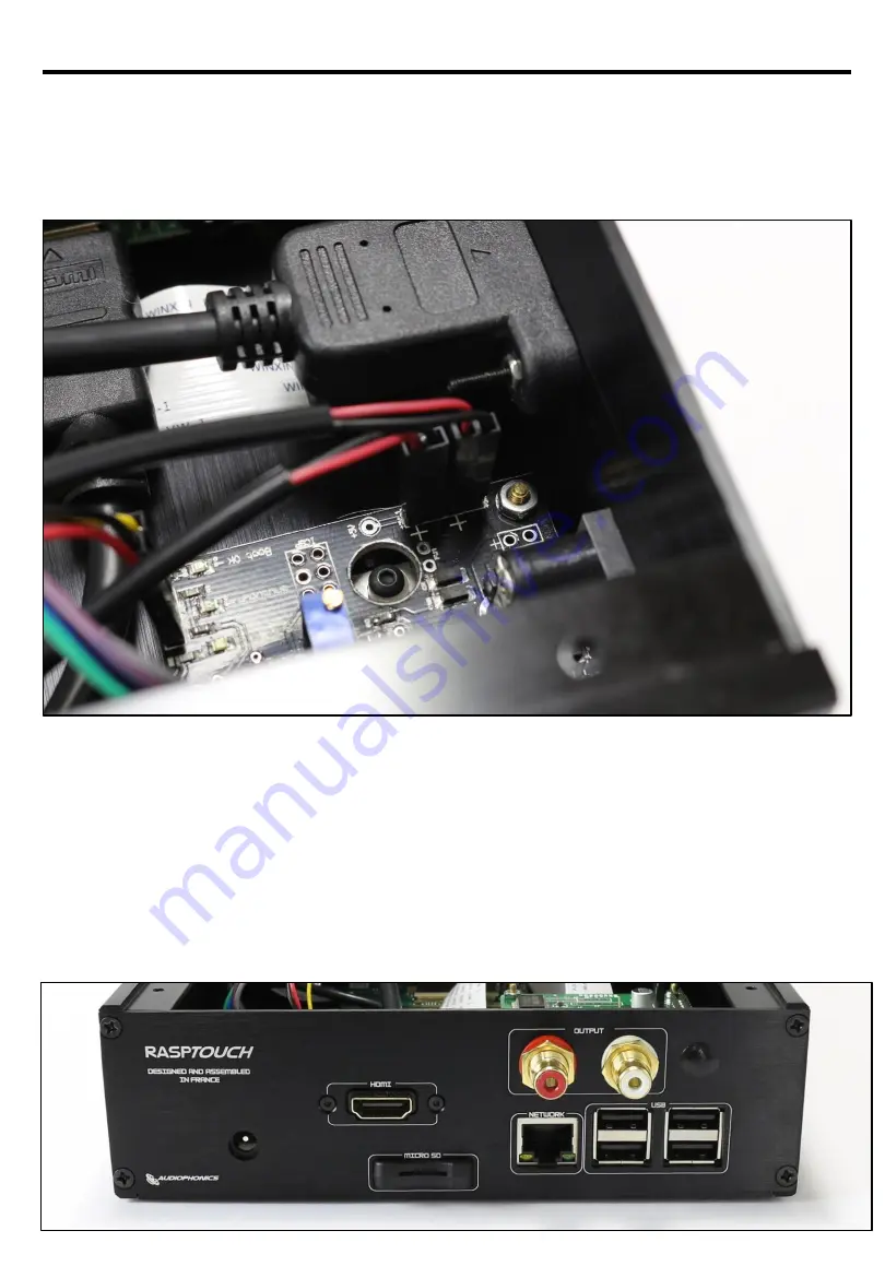
Here are the connections of the 2 micro USB cables (Corresponding to the Raspberry Pi and PCB of 
the touchscreen), to the ATX power control.


Be sure to connect each red cable to the terminal marked "+" on the PCB. 
See photo below. 

14 – Power supply of the Rasptouch with DAC ES9018K2M…


The entire system is powered by the ATX power control (it is powered from 7 to 12V / 2A). Indeed, 
the Jack is accessible from the back panel (see picture below), and will enable you to feed all the 
components: 

DAC ES9018K2M 

Raspberry Pi 

Official Raspberry (via PCB) 

Pushbutton with LED 

Summary of Contents for RASPTOUCH ES9018K2M

Page 1: ...RASPTOUCH Open source network player Raspberry Pi 3 DAC User Manual Kit DIY ES9023 or ES9018K2M...

Page 2: ...avoid any erroneous manipulation an to protect you and the device from possible dammages caused by inadequate use we invite you to follow step by step the assembly of the case the mounting of the scre...

Page 3: ...lect the following pieces RASPTOUCH 1 Elements necessary for mounting the case and the display support Display support Black and silver Cover Bottom all the holes to fixe all the components Left Side...

Page 4: ...First step mounting both sides on the bottom plate with 4 screws RASPTOUCH 2 Assembling the two sides Page 3 sur 29...

Page 5: ...Select the following elements RASPTOUCH 3 Display support Screw the two holding bars onto the support as in the picture Page 4 sur 29...

Page 6: ...ay support to the front of the pre assembled case then screw the 2 holding bars from the outside the final result should like the picture bellow RASPTOUCH 4 Assembling the display support Inside vue P...

Page 7: ...y unscrew the pre assembled display support To start mount the display on the support with the help of the 4 screws Then use the 4 M2 5x8mm spacers and the HU Inox A2 M2 5x2mm nuts for the display PCB...

Page 8: ...lose attention to how you connect the screen o the PCB Gently unlock the plastic wedge please check the following picture Once again please check if all the interconnect cables are like in the picture...

Page 9: ...tside if necessary please refer again to the step 4 Alayw pay close attention to avoid deconnecting the interconnect cables RASPTOUCH 7 Assembling the display with the support Screw the display PCB wi...

Page 10: ...o SD Extension HDMI push button Select the following elements to continue to the next step Push button HDMI Extension Micro SD Extension Micro SD Extension reader support bar HU Acier M2 Nuts THFC M2x...

Page 11: ...Micro should present them like the photo bellow Please screw the screws and nuts like the photo including the Micro SD Reader metal bar Keep in mind the Micro SD card reader are fixed using the two s...

Page 12: ...to remove the nut and then insert him in the hole Use the nut to place the button in the right position like the photo Don t forget to turn the button until he is in the right position It should looke...

Page 13: ...RASPTOUCH DAC ES9023 Page 12 sur 29...

Page 14: ...Pi wiil then stick to it The location is provided so that it lands perfectly where the heat is to be dissipated Please dont forget to remove the protection from the thermal paste 10 Raspberry Pi DAC...

Page 15: ...RASPTOUCH Do not be affraid to toghten the screws and spacers the goal is that the two parts become stable and fixed together Page 14 sur 29...

Page 16: ...ble to integrate the Raspberry Pi and the DAC in the case in te location provided for withe all the holes located loke in the picture The assembly is screwed by the bottom of the case withe 4 screws T...

Page 17: ...bled accessories and cables HDMI extension cable Micro SD Extension Cable and the Touchscreen interconnection as in the following pictures Be careful when inserting the interconnecting cable into the...

Page 18: ...as shown in the following picture Pushbutton the 2 pins on the inside on the right side of the PIN Insert Button on the PCB The other 2 wires for the LED external pins on the left side of the PIN PCB...

Page 19: ...he AC adapter 6 5 7V 2A you received in your package Indeed the jack present on the ES9023 DAC is accessible from the back panel see picture below and you will be able to feed all the components DAC E...

Page 20: ...RASPTOUCH DAC ES9018K2M Page 19 sur 29...

Page 21: ...i wiil then stick to it The location is provided so that it lands perfectly where the heat is to be dissipated Please dont forget to remove the protection from the thermal paste 10 Raspberry Pi DAC ES...

Page 22: ...RASPTOUCH Do not be affraid to toghten the screws and spacers the goal is that the two parts become stable and fixed together Page 21 sur 29...

Page 23: ...able to integrate the Raspberry Pi and the DAC in the case in te location provided for withe all the holes located loke in the picture The assembly is screwed by the bottom of the case withe 4 screws...

Page 24: ...sories and cables HDMI extension cable Micro SD Extension Cable and the Touchscreen interconnection and both USB cables as in the following pictures Be careful when inserting the interconnecting cable...

Page 25: ...ment Once the Raspberry DAC ES9018K2M assembly is fitted it is time to put in place the ATX power control and connect all the cables Page 24 sur 29 In the picture above you have the ATX ready to use a...

Page 26: ...and as shown on the diagram The PIN marked G on the DAC PCB remains unused DO NOT FORGET Add a thermal paste sold separately to the underside of the ATX Power control to dissipate heat during use As...

Page 27: ...onnections with its light symbol to the ATX power control For the pushbutton the 2 pins on the inside on the right side of the PIN mark Button on the PCB The other 2 wires for the LED external pins on...

Page 28: ...red cable to the terminal marked on the PCB See photo below 14 Power supply of the Rasptouch with DAC ES9018K2M The entire system is powered by the ATX power control it is powered from 7 to 12V 2A Ind...

Page 29: ...SD x1 screws x2 Holding bar for screen holder x2 Cap nylon cover for hole diameter 7 9mm HDMI wall socket to HDMI female 30cm Power cable Micro USB male angled 20cm x2 Pushbutton aluminum black cylin...

Page 30: ...ces be liable for any incidental or consequential damages arising from the loss of property or other damage or losses due to the failure of an Audiophonics product Audiophonics is not liable for loss...

Reviews: