7
4.0 f u n c t i o n a l t e s t s
4.2
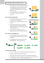
Functional test procedure
For test point
(TP)
references, see section 6.0 Test Points.
No
4.2.1.
4.2.2.
4.2.3.
4.2.4.
4.2.5.
4.2.6.
4.2.7.
4.2.8.
4.2.9.
Action
Disconnect all
cables from
amplifier
Check voltage
setting
Check fuse
type
Check fuse
resistance
Set up power
supply
Remove cover
Connect
supplies as
shown in
Figure 4.1
Apply DC
voltage to
amplifier
Measure left
channel supply
rails
Test Equipment
Multimeter set
to
Ω
Dual tracking DC
power supply
Dual tracking DC
power supply
Dual tracking DC
power supply
Multimeter set to
V DC
Details
Read ratings label on rear of amplifier.
Open fuse holder in power socket on rear
panel.
Rated supply
Fuse Type
230 V AC
T2.5A L250V
115 V AC
T4A 125V
110 V AC
T4A 125V
Fuse and spare fuse should be low
resistance.
Set output voltage to ±32 V, current limited
to 500 mA.
With supplies off, connect
•
positive output of supply to positive
terminal of reservoir capacitor
•
negative output of supply to
negative terminal of capacitor
No connection is required to 0 V terminal
of power supply.
CAUTION:
Do not connect with wrong polarity.
Check supply outputs are ±32 V and
switch output on.
Current output should be
<300 mA negative supply and
<600 mA positive supply.
If higher, turn RV701
(TP 24)
and RV801
(TP 25)
fully anti-clockwise.
Continue with test procedure of current
output is 180 mA ±25 mA negative supply
and 515 mA ±25 mA positive supply.
If higher, switch off and investigate.
Measure voltage across D713
(TP 1+ and
TP 1-)
and D714
(TP 2+ and TP 2-)
.
Voltage should be 32 V ±0.25 V.
Summary of Contents for 8000S
Page 1: ...service manual Integrated amplifier 8000S ...
Page 25: ...25 7 0 c i rc u i t s c h e m a t i c s 7 9 Digital system interface schematic SCH26701 03 01 ...
Page 27: ...27 7 0 c i rc u i t s c h e m a t i c s 7 11 Relay coils schematic SCH26701 05 01 ...
Page 28: ...28 7 0 c i rc u i t s c h e m a t i c s 7 12 Front panel schematic SCH26702 01 01 ...
Page 29: ...29 7 0 c i rc u i t s c h e m a t i c s 7 13 Speaker outputs schematic SCH26703 01 01 ...


