


0.0V
10.3V
12.0V
-12.0V
-0.5V
0.4V
0.4V
0.0 V
11.1V
10.9V
42.4V
12.0V
43.0V
41.8V
-8.0V
-11.6V
-12.0V
-42.4V
-43.0V
-44.0V
44.0V
-11.6V
10.3V
11.5V
11.5V
10.9V
TP 5+
TP 5-
TP 2+
TP 24
TP 6+
TP 6-
TP 2-
TP 1+
TP 9
TP 1-
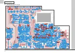
20.1
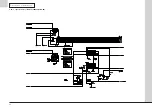
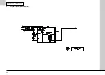
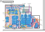
7.0 c i r c u i t s c h e m a t i c s
7.4.1 Power amplifier left channel schematic (SCH26701-09-02)
All DC voltages are relative to 0 V.
Measurements should be made with no connections to
amplifier except AC power.
Use high input impedance voltmeter (>20 k
Ω
/V).
Meter must be “floating” relative to ground.
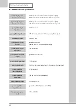
Summary of Contents for 8000S
Page 1: ...service manual Integrated amplifier 8000S ...
Page 25: ...25 7 0 c i rc u i t s c h e m a t i c s 7 9 Digital system interface schematic SCH26701 03 01 ...
Page 27: ...27 7 0 c i rc u i t s c h e m a t i c s 7 11 Relay coils schematic SCH26701 05 01 ...
Page 28: ...28 7 0 c i rc u i t s c h e m a t i c s 7 12 Front panel schematic SCH26702 01 01 ...
Page 29: ...29 7 0 c i rc u i t s c h e m a t i c s 7 13 Speaker outputs schematic SCH26703 01 01 ...