background image

Installation Manual 

38 

Document #: LTRT-59811 


MediaPack Series 


8. 

In the ‘Gateway’ field, enter the IP address of the default gateway (if any). 

9. 

Click 

Apply 

10. 

Click 

to save the new client. 

OK

11. 

Physically reset the device using the hardware reset button (or power down and then 
power up the device). This causes the device to use BootP; the device changes its 
network parameters to the values provided by BootP. 

; the ‘Client Configuration’ screen closes. 

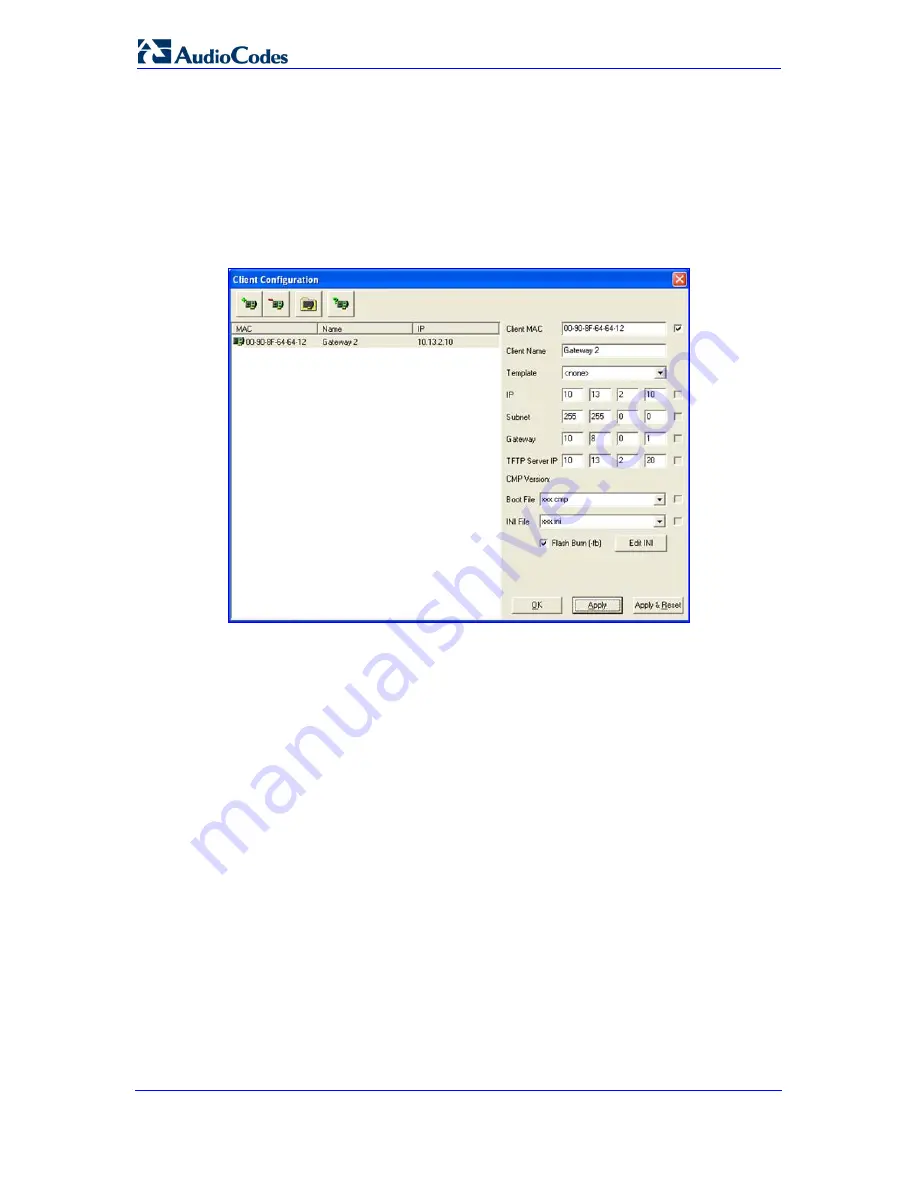
Figure 3-2: BootP Client Configuration Screen 


3.1.3 

Assigning an IP Address Using the Voice Menu Guidance 

Initial configuration of the device can be performed using a standard touch-tone telephone 
connected to one of the FXS ports. The voice menu can also be used to query and modify 
basic configuration parameters. 


To assign an IP address using the voice menu guidance: 

1. 

Connect a telephone to one of the FXS ports.  

2. 

Lift the handset and dial 

***12345

3. 

Wait for the 'configuration menu' voice prompt to be played. 

 (three stars followed by the digits 1, 2, 3, 4, and 5). 

4. 

To change the IP address: 

a. 

Press 

followed by the pound key (

#

b. 

Press the 

); The current IP address of the device is 

played.  

#

c. 

Dial the new IP address. Use the star (*) key instead of periods (.), e.g., 
192*168*0*4, and then press 

 key. 

#

d. 

Review the new IP address, and then press 

 to finish. 

5. 

To change the subnet mask: 

to save. 

a. 

Press 

2

 followed by the 

key; The current subnet mask of the device is played.  

Summary of Contents for MediaPack MP-118

Page 1: ...Document LTRT 59811 March 2010 Installation Manual Version 6 0...

Page 2: ......

Page 3: ...nts 24 2 2 3 Mounting the MP 124 24 2 2 3 1 Desktop Mounting 24 2 2 3 2 19 inch Rack Mounting 25 2 2 4 Cabling the MP 124 26 2 2 4 1 Power Surge Protection and Grounding of MP 124 27 2 2 4 2 Connectin...

Page 4: ...Installation Manual 4 Document LTRT 59811 MediaPack Series 4 Monitoring the Device 55 4 1 Front Panel LEDs 55 4 2 Web Interface 56 4 2 1 Viewing Alarms 56 4 2 2 Viewing Channel Status 57...

Page 5: ...nting 24 Figure 2 17 MP 124 with Brackets for Rack Installation 25 Figure 2 18 Grounding and Power Surge Protection 28 Figure 2 19 RJ 45 Connector Pinouts 29 Figure 2 20 50 pin Telco Connector MP 124...

Page 6: ...el 22 Table 2 5 MP 124 Rear Panel Component Descriptions 23 Table 2 6 MP 124 Rear Panel Ethernet LEDs Description 23 Table 2 7 Pin Allocations of the 50 pin Telco Connector 30 Table 3 1 Default IP Add...

Page 7: ...yright 2010 AudioCodes Ltd All rights reserved Date Published March 17 2010 Trademarks AudioCodes AC AudioCoded Ardito CTI2 CTI CTI Squared HD VoIP HD VoIP Sounds Better InTouch IPmedia Mediant MediaP...

Page 8: ...x refers to MP 118 MP 114 and MP 112 devices Note The MP 11x and MP 124 devices are indoor units and therefore must be installed only indoors However the MP 124 FXS telephony cables are outdoor compli...

Page 9: ...e voltage and ringing current supplied from the CO or the PBX just like an analog telephone An FXO VoIP device interfaces between the CO PBX line and the Internet FXS Foreign Exchange Station is the i...

Page 10: ...Installation Manual 10 Document LTRT 59811 MediaPack Series Reader s Notes...

Page 11: ...tial and basic setup of the device including hardware installation and software configuration The flowchart below summarizes these steps Figure 1 1 Required Steps to Install the Device Notes For detai...

Page 12: ...Installation Manual 12 Document LTRT 59811 MediaPack Series Reader s Notes...

Page 13: ...describes the MP 11x hardware installation 2 1 1 Physical Description The subsections below provide a physical description of the front and rear panels of the MP 11x 2 1 1 1 MP 11x Front Panel The dev...

Page 14: ...wer supply socket 100 240 0 3A max 2 10 100Base TX Uplink port Ethernet 3 RS 232 status port requires a DB 9 to PS 2 adaptor RS 232 Note 4 MP 112 does not provide a serial port FXS and or Provides two...

Page 15: ...g the MP 11x The device can be mounted in one of the following ways Desktop mounting refer to Desktop Mounting 15 on page Wall mounting refer to Wall Mounting 16 on page Standard 19 inch rack mounting...

Page 16: ...MP 11x on them 2 1 3 3 19 inch Rack Mounting The MP 11x can be installed in a standard 19 inch rack by placing it on an AudioCodes 19 inch rack mounting shelf special customer order that must be pre i...

Page 17: ...FXO Devices 18 on page Cabling the FXS Lifeline refer to Cabling the MP 11x FXS Lifeline 19 on page Serial connection to a computer refer to Connecting MP 11x RS 232 Port to a PC 20 on page Connecting...

Page 18: ...cable it differently 2 1 4 2 Connecting MP 11x to FXS FXO Devices Follow the procedure below for connecting MP 11x to FXO or FXS devices Warnings Ensure that you connect FXS ports only to analog tele...

Page 19: ...to corresponding FXO ports i e FXS Port 1 to FXO Port 5 FXS Port 2 to FXO Port 6 and so on For devices providing only FXO ports A Lifeline is not available Note The use of the Lifeline upon network f...

Page 20: ...ports Figure 2 10 Lifeline Cabling for FXS and FXO Devices 2 1 4 4 Connecting MP 11x RS 232 Port to a PC Follow the procedure below to connect the MP 11x serial RS 232 interface to a PC using a straig...

Page 21: ...ablishing a serial communications link with MP 11x refer to Assigning an IP Address Using the CLI on page 41 2 1 4 5 Connecting MP 11x to Power The MP 11x is powered from a standard AC electrical outl...

Page 22: ...for indicating various operating statuses In addition the front panel provides a reset button described in the table below For a description of the device s LEDs refer to Monitoring Front Panel LEDs...

Page 23: ...mandatory for all installations Accepts a 6 32 UNC screw 2 100 250 V 50 60 Hz 2A or The MP 124 can be ordered with one of the following power configurations 48V 1 3A AC power provides an AC power sup...

Page 24: ...ith two crimping screws depending on ordered model Two short equal length brackets and bracket to device screws for 19 inch rack installation Regulatory Information document 5 Check retain and process...

Page 25: ...ent compatible with the maximum ambient temperature Tma of 40 C 104 F Reduced Air Flow Installation of the equipment in a rack should be such that the amount of air flow required for safe operation on...

Page 26: ...ing the MP 124 This section describes the MP 124 cabling procedures Grounding earthing MP 124 refer to Grounding the MP 124 26 on page Connecting to the Ethernet network refer to Connecting MP 124 to...

Page 27: ...n establish that MP 124 does not comply to the standards specified above and MP 124 is within the hardware warranty period Lightning is the transient passage of electrical current between a cloud and...

Page 28: ...of the foundation reinforcement conductor Before installation loop testing grounding measurements must be done by a certified electrician to verify the quality of the grounding connection The groundin...

Page 29: ...rnet network Using a crossover Ethernet cable with RJ 45 connectors on either end connect the MP 124 Ethernet port labeled ETHERNET Figure 2 19 RJ 45 Connector Pinouts directly to the network For RJ 4...

Page 30: ...ct MP 124 to the FXS telephone interface 1 Wire the 50 pin Telco connectors according to the pinouts in the table below Table 2 7 Pin Allocations of the 50 pin Telco Connector Phone Channel Connector...

Page 31: ...4 rear panel labeled Analog FXS Lines 1 24 5 Connect the telephone lines from the MDF adaptor block to a fax machine modem or telephones by inserting each RJ 11 connector on the 2 wire line cords of t...

Page 32: ...Connect the DB 9 connector refer to the figure below for connector pinouts on one end of the cable to the MP 124 RS 232 port labeled RS 232 2 Connect the DB 9 connector refer to the figure below for c...

Page 33: ...o the Regulatory Information document supplied with the device Use only the AC power cord supplied with the device To connect MP 124 to the AC power supply Connect the MP 124 AC power socket located o...

Page 34: ...into the DC inlet on the MP 124 rear panel and then secure it to the device by fastening the two adaptor to panel screws located on the terminal block Figure 2 23 Wired DC Power Terminal Block Connec...

Page 35: ...XO devices 10 1 10 10 FXO device 10 1 10 11 Note FXO interfaces are applicable only to MP 11x series devices 255 255 0 0 Subnet Mask 0 0 0 0 Default Gateway IP Address To assign an IP address to the d...

Page 36: ...IP address and subnet mask Connect the network interface on your PC directly to the device using an Ethernet crossover cable for default IP addresses refer to Assigning an IP Address on page 35 3 Acc...

Page 37: ...vice using the supplied AudioCodes BootP TFTP Server application Notes BootP procedure can also be performed using any standard compatible BootP server For a detailed description of BootP refer to the...

Page 38: ...rmed using a standard touch tone telephone connected to one of the FXS ports The voice menu can also be used to query and modify basic configuration parameters To assign an IP address using the voice...

Page 39: ...onfiguration menu voice prompt to be played three stars followed by the digits 1 2 3 4 and 5 5 Dial 31 followed by the 6 To change the IP address perform the following key the current IP address is pl...

Page 40: ...p print Content type text plain n n print INI file generator CGI n print Request for MAC mac IP ip n n print EOF SyslogServerIP 36 44 0 15 EnableSyslog 1 SSHServerEnable 1 EOF The table below lists th...

Page 41: ...on link with the device using the following communications port settings Baud Rate 9 600 bps for MP 11x 115 200 bps for MP 124 Data Bits 8 Parity None Stop Bits 1 Flow Control The CLI prompt appears N...

Page 42: ...xy Registration Set the Use Default Proxy field to Yes Optional In the Proxy Name field enter the Proxy s name The Proxy name replaces the Proxy IP address in all SIP messages This means that messages...

Page 43: ...channels 1 through 8 and then in the Phone Number column enter the phone number e g 101 for the first channel Phone numbers 102 103 104 and so on are sequentially assigned to subsequent channels i e...

Page 44: ...to the same device To make a call between the two devices off hook phone 101 and at the dial tone dial 120 To make a call between the two phones connected to device 10 33 24 18 off hook phone 101 and...

Page 45: ...flash You can also gracefully lock the device so that no new calls are allowed and existing calls are terminated only after a user defined period This is useful when for example you are uploading new...

Page 46: ...e Configuration tab Security Settings menu WEB User Accounts Figure 3 7 WEB User Accounts Page for Users with Security Administrator Privileges 2 To change the user name perform the following a In the...

Page 47: ...e the device s configuration by loading the previously saved ini file or by simply loading a newly created ini file Note When loading an ini file using this Web page parameters not included in the ini...

Page 48: ...ace s login user name and password These default settings include factory defaults as well as user defined defaults refer to the device s User s Manual Notes The device resets to the software version...

Page 49: ...ng configuration running on the device cmp Mandatory compressed firmware file ini Optional Configuration file Auxiliary files Optional CPT Call Progress Tone PRT Prerecorded Tones and USERINF User Inf...

Page 50: ...refer to the note above 2 Open the Software Upgrade Wizard Management tab Software Update menu Software Upgrade Wizard Figure 3 9 Start Software Upgrade Wizard Screen the Software Upgrade Wizard page...

Page 51: ...ini Use the file is loaded to the device and you re notified as to a successful loading ini file currently used by the device by not selecting an ini Return the device s configuration settings to fact...

Page 52: ...uded in the ini file Parameters not specified in the ini Dial Plan file are reset to factory default values Dial plan file Call Progress Tones This is a region specific telephone exchange dependent fi...

Page 53: ...Page 2 Click the Browse button corresponding to the file type that you want to load navigate to the folder in which the file is located and then click Open the name and path of the file appear in the...

Page 54: ...Installation Manual 54 Document LTRT 59811 MediaPack Series Reader s Notes...

Page 55: ...ook position Uplink Ethernet Link Status Green On Valid 10 100Base TX Ethernet connection Off No uplink Fail Failure Indication Red On Failure fatal error or system initialization Off Normal working c...

Page 56: ...k access to viewing active alarms 4 2 1 Viewing Alarms The Home page allows you quick access to the Active Alarms page typically accessed from the Status Diagnostics tab Status Diagnostics menu Active...

Page 57: ...the device s User s Manual Figure 4 2 MP 11x Home Page Figure 4 3 MP 124 Home Page Table 4 3 Color Coding of Channel Status Icon Icon State Color Description Red Line not connected only applicable to...

Page 58: ...Installation Manual Version 6 0 www audiocodes com...

Reviews: