background image

- 6 -

A10-TX User Guide

Powering 

The A10-TX is powered by two AA (LR6) batteries. For the longest runtime, use Lithium pri

-

mary cells. The transmitter also accepts alkaline primary and Nickel Metal Hydride rechargeable 

batteries. Select the battery type used in the menu to ensure that the battery condition is indicated 

accurately in both the transmitter display and receiver. 

1. 

Open the battery compartment by simultaneously pressing both mechanical releases of the 

battery door latch. (

See Figure 1.

2. 

Insert two fresh AA type (LR6) batteries. Note correct battery polarity. 

3. 

Momentarily press the red On/Off button. The blue power LED will light and the display will 

illuminate. The transmitter is now powered on. 

4. 

To turn the transmitter off, press and hold the red button until the “turning off’ progress bar 

completes and the unit goes dark. 

Main Display 

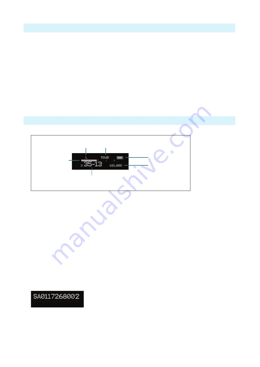
After powering on the A10-TX the display shows the following.

Battery Condition

Input 

Gain

RF Output 

Power

Frequency in MHz

Frequency as

Region–Channel–Sub Channel

Input Level 

Meter

•  RF Output Power

 - three power levels are indicated, 

L

ow (10 mW), 

M

edium (20 mW), 

H

igh (50 mW) 

•  Input Gain

 - gain applied to the input source, in dB 

•  Battery Condition

 - shows the battery voltage level of the transmitter batteries, five-seg

-

ments 

•  Frequency in MHz

 - the transmitting frequency is shown 

•  Frequency in Region–Channel–Sub Channel

 - the transmitting frequency is shown in 

region, channel, and sub channel.


ª

 X, Y, and Z regions are selected by the TV Channel Map setting.

•  Input Level Meter

 - shows audio input signal level 

Press the Left button, to view the name of the transmitter. The serial number of the transmitter 

is the default name of the transmitter. The transmitter name may be changed via the A10-TX 

Remote app. 


By pressing the Right button, the user can view the recording status, which displays the current 

file name, time elapsed, time remaining, timecode and current frame rate. 

Summary of Contents for A10-TX

Page 1: ...A10 TX Digital Transmitter User Guide ...

Page 2: ...Timecode Clock 12 Timecode Output 13 Remote Control 13 Firmware Updates 14 Specifications 14 Input Connector Wiring Diagram 15 Battery Runtime Chart 15 Certifications 15 Industry Canada Conformity 15 FCC Conformity 16 Minimize RF Exposure 16 Frequency Tables 17 X Frequencies 6 MHz Per TV Channel 17 Y Frequencies 7 MHz Per TV Channel 18 Z Frequencies 8 MHz Per TV Channel 19 Channel Assignments by R...

Page 3: ...me renowned for and with extremely low end to end latency of 2 mS The A10 TX has an intuitive menu system allowing the user to become familiar with settings within a few minutes of turning it on Key Features Low noise studio grade balanced input for microphones and line level signals with analogue limiter and phantom power Fully digital RF transmission Ultra accurate timecode generator jam synched...

Page 4: ...evel are set based on the input type At the Transmitter 1 Attach the straight antenna to the A10 TX 2 Attach an audio source to the 3 pin LEMO input connector 3 Insert AA batteries into the A10 TX battery compartment and power on the unit with the red On Off button 4 Set the audio input type to set to match the connected input 5 Set the transmitting frequency on the A10 TX match the frequency set ...

Page 5: ...to the left or decre ments values 5 Power Button Press to power on the unit Press and hold to power down the unit 6 Audio Input Connector Balanced LEMO 3 connector Accepts mul tiple audio input types including unbalanced lavalier balanced microphone balanced line Also used for timecode input and output 7 Input Overload LED Red LED illuminates when clipping occurs 8 Menu Button Enters the menu sele...

Page 6: ...ter powering on the A10 TX the display shows the following Battery Condition Input Gain RF Output Power Frequency in MHz Frequency as Region Channel Sub Channel Input Level Meter RF Output Power three power levels are indicated Low 10 mW Medium 20 mW High 50 mW Input Gain gain applied to the input source in dB Battery Condition shows the battery voltage level of the transmitter batteries five seg ...

Page 7: ...dent Gain control is in 1 dB increments Lav 0 dB to 40 dB Line Setting 10 to 16 dB Mic setting 16 to 40 dB w 20dB pad Mic setting 36 to 60 dB Audio Setup Enters the Audio Setup sub menu Low Cut Limiter Lav Mic Line Record TC Enters the Record TC sub menu Record File Info TX Record Mode Timecode Frame Rate Privacy Activates transmission privacy with a four number key set on the transmitter and rece...

Page 8: ...tus is remembered across sleep and power cycles File Info Shows important information about the file being recorded Time Elapsed Time Remaining Timecode File Name TX Record Mode Select the operational mode of the A10 TX TX Rec simultaneous wireless transmission and recording RecOnly recording function only Timecode Enter Timecode menu Timecode values from either the attached external timecode gene...

Page 9: ...display ideal for when transmitter is attached upside down on boom pole Normal default Flipped System Menu Selections Icon Description Options Exit Returns to the main menu Sleep When selected the A10 TX goes into low power Sleep mode The blue LED flashes when the unit is in a sleep state The unit returns to normal power operation when any button is pressed or the transmitter is activated from the...

Page 10: ... television channels used in geographic regions Depend ing on the selected channel mapping channels cover 6 7 or 8 MHz Sub Channel channels are divided in 400 kHz increments called sub channels to speed up frequency selection The number of sub channels depends on the channel mapping selected Tune specific frequencies within the transmitter s tuning range can be selected in 25 kHz increments To cha...

Page 11: ...r is active only on the strongest peaks Antenna The SMA antenna connector is used to mount the included 1 4 wave whip antenna The use of any other type is forbidden For best operation and transmission power with the included 1 4 wave antenna keep it in the free field If worn on a body keep the antenna away from direct contact with the wearer s body Recording The A10 TX incorporates a data recorder...

Page 12: ...he A10 TX design incorporates a supercapacitor to power the time of day clock for several days in the absence of batteries The supercapacitor reaches full charge when batteries have been in the unit for five minutes Time of Day Clock The time and date clock holds time and date for files recorded on the A10 TX and can be used for the Time of Day timecode value To set time and date 1 Enter the Selec...

Page 13: ...ee download from the Google Play store and iOS App store respectively With the A10 TX Remote app you can 1 Change the transmitter s name it is set to the transmitter s serial number by default 2 View timecode and frame rate 3 Monitor Sleep status Battery status Bluetooth signal strength and Record status 4 Turn Sleep mode On Off 5 Start Stop recording at the transmitter 6 Adjust Gain 7 Set the low...

Page 14: ...oad the new firmware update file from the Audio Ltd website and copy the file onto an approved microSD card that has been formatted in the A10 TX 2 Insert the microSD card in the unit 3 Insert fresh AA batteries in the unit 4 Enter the System menu and choose Update The unit will indicate the revision of firmare to update 5 Confirm that you want to update This starts the update process 6 Do not pow...

Page 15: ... 20 dB pad Bal Line 3k 24 dBu Low Frequency Cut Off 40 Hz 60 Hz 80 Hz 100 Hz 200 Hz user selectable Input Limiter Analogue pre A D converter Input Type Microphone or line level balanced or unbalanced Bias and Phantom Power 5 V Bias 12 V or 48 V phantom power Menu and Controls OLED menu display 3 button navigation Recording File Format Audio Ltd proprietary mic data file requires conversion to WAV ...

Page 16: ...Operation is subject to the following two conditions 1 this device may not cause interference and 2 this device must accept any interference including interference that may cause undesired operation of the device FR Le présent appareil est conforme aux CNR d Industrie Canada applicables aux appareils radio RSS 210 L exploitation est autorisée aux deux conditions suivantes 1 l appareil ne doit pas ...

Page 17: ...e Declaration of Conformity documentation is provide online at http audioltd com doc Before putting the products into operation please observe the respective country specific regulations Minimize RF Exposure To avoid the possibility of exceeding the FCC RF exposure limits body worn operations are restricted to belt clips holsters or similar accessories that have no metallic component in the assemb...

Page 18: ...4 559 8 29 560 2 560 6 561 561 4 561 8 562 2 562 6 563 563 4 563 8 564 2 564 6 565 565 4 565 8 30 566 2 566 6 567 567 4 567 8 568 2 568 6 569 569 4 569 8 570 2 570 6 571 571 4 571 8 31 572 2 572 6 573 573 4 573 8 574 2 574 6 575 575 4 575 8 576 2 576 6 577 577 4 577 8 32 578 2 578 6 579 579 4 579 8 580 2 580 6 581 581 4 581 8 582 2 582 6 583 583 4 583 8 33 584 2 584 6 585 585 4 585 8 586 2 586 6 5...

Page 19: ... 1 579 5 579 9 580 3 580 7 581 1 581 5 581 9 582 3 582 7 36 583 3 583 7 584 1 584 5 584 9 585 3 585 7 586 1 586 5 586 9 587 3 587 7 588 1 588 5 588 9 589 3 589 7 37 590 3 590 7 591 1 591 5 591 9 592 3 592 7 593 1 593 5 593 9 594 3 594 7 595 1 595 5 595 9 596 3 596 7 38 597 3 597 7 598 1 598 5 598 9 599 3 599 7 600 1 600 5 600 9 601 3 601 7 602 1 602 5 602 9 603 3 603 7 39 604 3 604 7 605 1 605 5 6...

Page 20: ... 8 584 2 584 6 585 0 585 4 585 8 586 2 586 6 587 0 587 4 587 8 588 2 588 6 589 0 589 4 589 8 36 590 2 590 6 591 0 591 4 591 8 592 2 592 6 593 0 593 4 593 8 594 2 594 6 595 0 595 4 595 8 596 2 596 6 597 0 597 4 597 8 37 598 2 598 6 599 0 599 4 599 8 600 2 600 6 601 0 601 4 601 8 602 2 602 6 603 0 603 4 603 8 604 2 604 6 605 0 605 4 605 8 38 606 2 606 6 607 0 607 4 607 8 608 2 608 6 609 0 609 4 609 ...

Reviews: