


6
Using the product with the ATDM-0604 Digital SmartMixer
For the firmware of ATDM-0604, please use Ver1.1.0 or later.
1. Connect Mic 1-4 of the product to input 1-4 on the ATDM-0604. Launch the ATDM-0604 Web Remote,
select “Administrator”, and log in.
2. Click the icon (
) on the top right of the screen then select Audio>Audio System. Activate "Virtual Mic
Mode". This will automatically turn the first 4 channels of the ATDM-0604 into virtual polar patterns
created from the input of the product.
In Setting & Maintenance Operator Access / Operator Page
Once “Virtual Mic Mode” is activated there will be an option to show or hide the “Array Mic Off” button
on the operator page. This button allows the operator to mute the mic and turn off the LED ring from the
operator page for temporary mute.
• This setting is not saved on the device, so rebooting the ATDM-0604 restores it to its default “Mic On”
position.
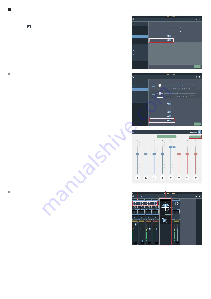
On the main Administrator page click on the input tab
1. Switch the input of the first 4 channels to Virtual Mic.
2. Adjust the gain to the required level. (a)
• Setting the input gain on one channel will simultaneously change it on all four channels. Low cut, EQ,
Smart Mixing and routing can individually be assigned for each channel or “Virtual Mic”.
3. Clicking on the side of the Virtual Mic box (b) opens the settings tab for the directivity lobe.
These can be adjusted between “Normal” (hypercardioid) , “Wide” (cardioid) and "Omni".
4. Clicking the blue button around the circle sets the orientation of each Virtual Mic.
5. Adjust the Virtual Mic. direction towards the source to be picked up.
• The Audio-Technica logo is located on the front of the microphone. The microphone must be oriented
correctly to operate properly.
6. Using the “Tilt” function, you can adjust the directivity on the vertical plane to adjust the angle depend-
ing on whether the talker is sitting or standing.
7. Adjust the individual volume of each Virtual Mic using the Volume Fader.
Settings & Maintenance
Operator Access
Presets
Logging
System Info
Preset
Board Meeting July
Meeting Room
General
Network
Audio
Front Panel
System Settings
Utilities
User Access
Apply
Delay Unit Type
Audio System
Ft
Output Flip
Gain Unit Type
dBu
Virtual Mic Mode
Operator Page
System Settings
Operator Access
Presets
Logging
System Info
Settings & Maintenance
Preset
Board Meeting July
Meeting Room
Apply
Fader Settings
Mic
Assign
1
2
3
4
5
6
ST
Show
Mic
Show
Max Volume
Max Volume
1
2
ST
Mic
Show
Max Volume
Mic
Show
Max Volume
Mic
Show
Max Volume
INPUT
OUTPUT
Assign
1
2
3
4
5
6
ST
1
2
ST
INPUT
OUTPUT
Assign
1
2
3
4
5
6
ST
1
2
ST
INPUT
OUTPUT
Assign
1
2
3
4
5
6
ST
1
2
ST
INPUT
OUTPUT
Assign
1
2
3
4
5
6
ST
1
2
ST
INPUT
OUTPUT
Operator Page Restrictions
Preset Recall
Resume Fader Position
Number of Presets
6
Mic
Assign
Show
Max Volume
Mic
Show
Max Volume
Mic
Show
Max Volume
Logout Button
Array Mic Switch
Assign
1
2
3
4
5
6
ST
1
2
ST
INPUT
OUTPUT
Assign
1
2
3
4
5
6
ST
1
2
ST
INPUT
OUTPUT
Assign
1
2
3
4
5
6
ST
1
2
ST
INPUT
OUTPUT
Board Meeting July
MIC
Speech
Hall
AUX
Video Chat
85
Meeting Room
Recording
MIC 1
MIC 2
Array Mic Off
Preset
Board Meeting July
Meeting Room
Input
Output
5
6
ST
2
1
3
4
Smart Mix
AEC
Copy
1
2
ST
1
2
ST
1
2
ST
1
2
ST
1
2
ST
1
2
ST
1
2
ST
Virtual Mic
Virtual Mic
Virtual Mic
Virtual Mic
Smart Mix
Active
Smart Mix
Active
Smart Mix
Active
Smart Mix
Active
Smart Mix
Active
Smart Mix
Active
OUT 1 AEC
OUT 1 AEC
OUT 1 AEC
OUT 1 AEC
OUT 1 AEC
OUT 1 AEC
Mute
Max Volume
Mute
Max Volume
Mute
Max Volume
Mute
Max Volume
Mute
Max Volume
Mute
Max Volume
Mute
Max Volume
-Inf
dB
-2.5
dB
-2.5
dB
-2.5
dB
-2.5
dB
-2.5
dB
+10
dB
4 Band EQ
4 Band EQ
4 Band EQ
4 Band EQ
4 Band EQ
4 Band EQ
4 Band EQ
+48V
EQ
EQ
EQ
EQ
EQ
EQ
EQ
+48V
Line +4dBu
Line -10dBV
+43
dB
+20
dB
LINE
Mic
Mic
+20
dB
Mic
+48
dB
+40
dB
Mic
+20
dB
-13
dB
Mic
Floor 2
Floor 2
Floor 2
Floor 2
Floor 2
Floor 3
Floor 3
+10
+5
0
-5
-10
-20
-40
-80
-∞
dB
+18
+6
-6
-24
-60
0
+12
-12
-30
+10
+5
0
-5
-10
-20
-40
-80
-∞
dB
+18
+6
-6
-24
-60
0
+12
-12
-30
+10
+5
0
-5
-10
-20
-40
-80
-∞
dB
+18
+6
-6
-24
-60
0
+12
-12
-30
+10
+5
0
-5
-10
-20
-40
-80
-∞
dB
+18
+6
-6
-24
-60
0
+12
-12
-30
+10
+5
0
-5
-10
-20
-40
-80
-∞
dB
+18
+6
-6
-24
-60
0
+12
-12
-30
+10
+5
0
-5
-10
-20
-40
-80
-∞
dB
+18
+6
-6
-24
-60
0
+12
-12
-30
+10
+5
0
-5
-10
-20
-40
-80
-
∞
+18
+6
-6
-24
-60
0
+12
-12
-30
dB
Virtual Mic
Tilt
Orientation
front
Pattern
Wide
(a)
(b)


