Battery Selection and Installation
An alkaline 9-volt battery is recommended. Make certain the
transmitter power switch is Off before installing or changing
batteries.
When inserting the battery,
observe correct polarity as
marked inside the battery compartment.
The transmitter
housings are designed to prevent incorrect installation of the
battery;
do not force the battery in.
Reversed batteries may
cause damage to the transmitter.
UniPak
Transmitter Battery Installation
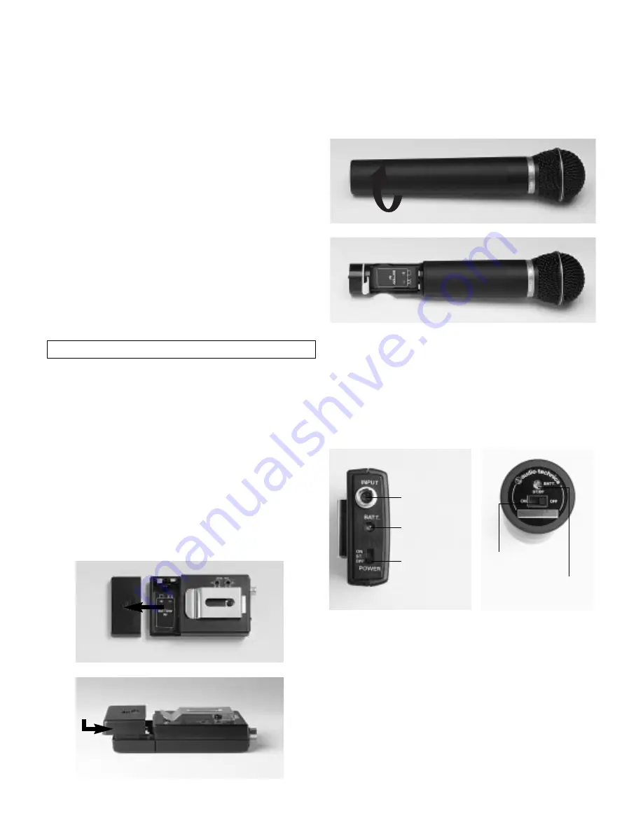
1. Slide off the battery cover as shown in Figure E.
2. Insert a 9V battery, observing correct polarity as marked
inside the battery compartment.
3. Replace the battery cover. Set the cover in place on the
transmitter as shown in Figure F, so it rests fully on the
case, then slide it forward firmly until it clicks closed.
(Cont. from pg. 2)
Attach the antennas to the antenna input jacks. The antennas
are normally positioned in the shape of a “V” (45° from
vertical) for best reception.
Do not try to move the antenna rod after the connector
shell has been tightened down. Always loosen the
connector shell completely before repositioning the rod.
If there is not sufficient space above the receiver and/or if the
receiver is installed in a metal cabinet, the antennas can be
mounted in the threaded holes in the back of the connectors
so the antennas will stick straight out from the back of the
receiver. Use one set of threaded holes or the other; do not
attempt to bend the antenna rods. The optional accessory
ATW-RA1 rack-mount antenna kit brings antenna inputs to the
front of the receiver. When two receivers are mounted side-
by-side in single 19" rack space, one ATW-RA1 is required for
each receiver.
Power Connections
Connect to a standard 120 volt 60 Hz AC power outlet. If
there is no AC power available, the back panel is equipped
with a jack for an external 12-18 volt DC source. The jack
takes a standard 2.5 mm I.D. coaxial DC power plug, center
negative
. Power from the DC input jack is switched by the
front-panel Power switch.
4
Handheld Transmitter Battery Installation
1. While holding the middle of the microphone body normally,
unscrew the battery cover (bottom 3" section) as shown in
Figure G.
2. Lift the white “battery keeper” arm and carefully insert a
fresh 9V alkaline battery, observing polarity markings
(Fig. H).
3. Replace the battery cover.
Do not overtighten.
Fig. G
Fig. H
Transmitter Setup
Battery Condition Indicator
After the battery is installed, turn the power on. The battery
condition indicator LED (Fig. I/J) should flash momentarily.
If it does not, the battery is installed incorrectly or it is dead.
If the indicator LED
stays
on (does not flash), the battery
voltage is low and the battery should be replaced. If this
happens during use, replace the battery immediately to
ensure continued operation.
UniPak Transmitter Input Connection
Connect an audio input device (microphone or guitar cable) to
the audio input connector on the bottom of the transmitter. A
number of Audio-Technica professional microphones and cables
are available separately, pre-terminated with a UniPak input
connector (see “Optional System Accessories” on page 6).
Fig. E
Fig. I
Fig. J
Input
Connector
Battery
Condition
Indicator
Power Switch
(Off/Standby/On)
Power Switch
(Off/Standby/On)
Battery Condition
Indicator
Fig. F


