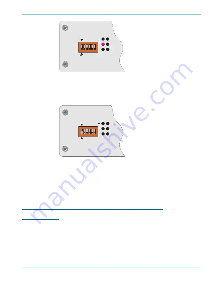
To use APIB to control ATS-2, select APIB on the rear-panel switch as
shown in Figure 24 (left-most switch clicked up to “1”), and connect a
cable from the APIB interface card on the controlling computer to the port
on ATS-2.
Whether controlled by APIB or GPIB, ATS-2 still uses APIB to control
other Audio Precision APIB instruments and accessories such as the
DCX-127 and the SWR-2122 family of switchers. Figure 25 illustrates how
to connect these devices to the ATS-2 when the GPIB port is the control
port; Figure 26 illustrates how to connect an APIB controller to this system
when the GPIB port is disabled.
Establishing GPIB Communication
GPIB Connection
The ATS-2 with Option GPIB installed has a 24-pin GPIB-compatible
connector on the rear panel. This D-shell connector conforms to the
mechanical requirements of IEEE-488.1-1987. The instrument is
connected to the instrument controller via an appropriate cable. The
instrument controller (a computer) must have a corresponding GPIB
interface port. Standard GPIB cables are designed so they can be stacked
if needed to connect multiple instruments into your GPIB system.
The GPIB Software Development Process
Chapter 7: GPIB Configuration
Getting Started with ATS-2
61
ERR
MAV
LA
TA
SRQ
GPIB
GPIB
4
0
1
2 1
8
16
APIB
ADDRESS
Figure 23. The ATS-2 Option GPIB panel; detail, shown in GPIB mode.
ERR
MAV
LA
TA
SRQ
GPIB
GPIB
4
0
1
2 1
8
16
APIB
ADDRESS
Figure 24. The ATS-2 Option GPIB panel; detail, shown in APIB mode.
Summary of Contents for ATS-2
Page 1: ...Getting Started with Your ATS 2 ATS 2 ...
Page 2: ......
Page 3: ...Getting Started with ATS 2 An Introductory Guide to ATS 2 APIB and GPIB Configurations ...
Page 8: ...iv Getting Started with ATS 2 ...
Page 16: ...Chapter 1 General Information Other Documentation for ATS 2 6 Getting Started with ATS 2 ...
Page 28: ...Chapter 3 Hardware Overview ATS 2 Rear Panel 18 Getting Started with ATS 2 ...
Page 66: ...Chapter 6 Specifications 56 Getting Started with ATS 2 ...


