background image

Wiring The Co-Pilot For 1997 models E350 models 

Red Wire (12volts)-Pin #1 

Locate the 

Red

 wire coming from the vehicle’s PCM Pin #

71.  

Tap this wire with the 

red       

Co-Pilot wire by soldering.  Shield the tap from the elements. 

Black Wire- Ground (GND) – PIN #9 

Locate the 

Black

 wire coming from the vehicle’s PCM Pin #

51

.  Tap this wire with the 

black


Co-Pilot wire by soldering.  Shield the tap from the elements. 

Green Wire- Vehicle Speed Sensor (VSS) – PIN #17 

Locate the VSS (Vehicle Speed Sensor) wire.  This 

Gray w/ Black

 stripe wire can be found at 

the PCM at pin #

58

 Run the green wire from the Co-Pilot module to the VSS wire and cut off 

any excess, but leave some slack.  Solder the Green Co-Pilot wire to the VSS wire and protect 

from elements, this is the most common install problem with wiring 

Summary of Contents for Co-Pilot

Page 1: ... While the Commander will still function perfectly on a stock transmission factory transmission shafts are weak and prone to breakage The factory torque converter clutch will also fail if applied under high load conditions Factory computers are programmed to disengage lockup under certain conditions which will protect the transmissions internal components under higher load This is when we recommen...

Page 2: ...nic board You will need a 1 16th inch hex Allen wrench to remove the face from the Co Pilot After the face has been removed the electronic board can be slid out of the casing from the front The digital face is attached to the circuit board with a ribbon cable do not force the board from the case There are four 4 switches on the circuit board the switches allow the user to select the features desir...

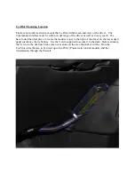
Page 3: ... have found the ideal place to locate the module is just to the right of the driver on the lower dash panel just above the right knee Use the Velcro supplied to secure it to the dash Before sticking the Velcro to the dash use brake clean or acetone on the area the sticker will be Run the Co Pilot wires that are to be wired up to the PCM Power train control module and the transmission through the f...

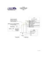
Page 4: ... be made in order for it to function properly There are several wires which are optional but still included to give the Co Pilot a more versatile use depending on your trucks current setup Use the diagram below as a reference when installing your Co Pilot to avoid any conflicts or confusion ...

Page 5: ...ng from the vehicle s PCM Pin 60 Tap this wire with the Black Commander wire by soldering Shield the tap from the elements Yellow Wire PCM PIN 10 and Blue Wire TCC PIN 11 Locate the vehicle s Torque Converter Clutch TCC wire coming from the vehicle s transmission This Purple w Yellow stripe wire can be found at the transmission connector passenger side of the transmission above the pan rail Cut th...

Page 6: ...e pan rail Tap by soldering the Green Co Pilot wire to the VSS wire and protect from elements A poor VSS connection is the most common wiring problem If at any time you would like to bypass the Co Pilot s operation simply unplug the wiring harness from the Co Pilot Module and jumper the harness blue and yellow terminals together with a paperclip Wiring The Co Pilot For 1994 5 1997 models The Co Pi...

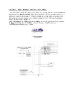
Page 7: ...NOT USED Orange Wire Pin 4 White Wire PIN 5 Pink Wire PIN 12 Purple Wire PIN 16 And Gray PIN 14 Red Wire 12volts Pin 1 ...

Page 8: ... connector to the wire leading back to the transmission and attach a butt connector to the wire heading to the vehicles computer PCM Reference the supplied wiring schematic before cutting wire Connect the Yellow wire coming from the Co Pilot to the wire that goes to the PCM Connect the Blue wire coming from the Co Pilot to the wire that goes to the transmission Protect the connections from the ele...

Page 9: ...hicle s PCM Pin 51 Tap this wire with the black Co Pilot wire by soldering Shield the tap from the elements Green Wire Vehicle Speed Sensor VSS PIN 17 Locate the VSS Vehicle Speed Sensor wire This Gray w Black stripe wire can be found at the PCM at pin 58 Run the green wire from the Co Pilot module to the VSS wire and cut off any excess but leave some slack Solder the Green Co Pilot wire to the VS...

Page 10: ...nd solder or attach a butt connector to the wire leading back to the transmission and attach a butt connector to the wire heading to the vehicles computer PCM Reference the supplied wiring schematic before cutting wire Connect the Yellow wire coming from the Co Pilot to the wire that goes to the PCM Connect the Blue wire coming from the Co Pilot to the wire that goes to the transmission Protect th...

Page 11: ......

Page 12: ...ose the problem Simply unplug the wiring harness from the back of the Commander module and put a bent paperclip into blue and yellow terminals of the harness plug jumper the blue and yellow together This reconnects the wire that you cut at the transmission plug and bypasses the Commander completely ...

Reviews: