


6
HYDRAULIC AND MECHANICAL INSTALLATION
Hydraulic fluid
Suitable seals type
Classification
Ref. Standard
Mineral oils
NBR, FKM, HNBR
HL, HLP, HLPD, HVLP, HVLPD
DIN 51524
Flame resistant without water
FKM
HFDU, HFDR
ISO 12922
Flame resistant with water
NBR, HNBR
HFC
Fluid viscosity
: 15 ÷ 100 mm
2
/s - max allowed range 2,8 ÷ 500 mm
2
/s
6.8 Filtration
The correct fluid filtration ensures a long service life of the valves and it prevent anomalous wearing or sticking.
CAUTION
Contamination in the hydraulic fluid may cause functional failures e.g. jamming or blocking of the valve spool / poppet.
In the worst case, this may result in unexpected actuators movements and thus it constitutes a risk of injury.
Ensure an adequate hydraulic fluid cleanliness according to the cleanliness class required for the the valve.
Max fluid contamination level,
see also filter section at www.atos.com or KTF catalog:
ISO4406 class 20/18/15 NAS1638 class 9
6.1 Power packs tank and tubes cleaning
The power unit tank has to be accurately cleaned, removing all the contaminants and any extraneous object.
When completely assembled an accurate washing of the piping (flushing) is requested to eliminate the contaminants.
6.2 Hydraulic connections
Flexible hoses are normally used on pressure line between powerpack and the valve and on user lines to connect the actuators. If their
potential breakage may cause damages to the machine or system or can cause injure to the operator, a proper retenction (as the chain
locking at both the pipe-ends) or alternately a protecting carter must be provided.
6.3 Hydraulic drains and return lines
Drain lines must be connected to the tank without counter pressure. The drain pipe must end above the oil level.
Return line has to be sized in order to avoid pressure peaks caused by istantaneous flow variations.
6.4 Fluid conditioning
A high-performance system must be thermally conditioned to ensure a limited fluid temperature excursion (generically between 40 and
50°C) so that the fluid viscosity remains constant during operation.
The machine working cycle should start after the prescribed temperature has been reached.
6.5 Air bleeds
Air in the hydraulic circuits affects the hydraulic stiffness and it causes malfunctioning and vibrations.
Following precautions have to be considered:
• at the system start-up all the bleeds must be released to allow the air removal
• untight the connections of the piping
• the system must be bled at first start-up or after maintenance
• a check valve (e.g. 0,5 bar) should be installed on the return line to tank to avoid emptying of the pipes following a long stop of the system
6.6 System flushing
The whole system must be flushed for a sufficient time in order to obtain the required minimum cleanliness level.
Make sure that also external pilot lines, if present in the system, are flushed.
A decisive factor for the flushing time is the contamination level of the hydraulic fluid which can only be determined by means of a particle
counter.
During the flushing procedure, perform a frequent monitor of the filters clogging indicator, replacing the filter elements when required.
6.7 Hydraulic fluids and operating viscosity range
Mineral oils type HLP having high viscosity index are recommended.
The hydraulic fluids must be compatible with the selected seals.
The type of fluid has to be selected in consideration of the effective working temperature range, so that the fluid viscosity remains at the
optimal level.
CAUTION: easily inflammable hydraulic fluid
In connection with fire or other hot sources, leaking hydraulic fluid may lead to fire or explosions.
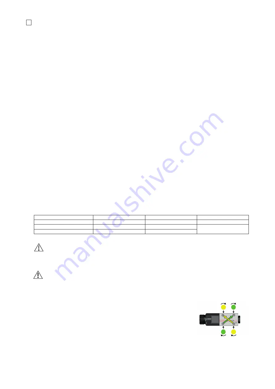
6.9 Valve fastening
Remove the protection pad located on the valve mounting surface.
Check the correct positioning of the seals on the valve ports.
Verify that the valve mounting surface is clean and free from damages and burrs.
Lock the fastening bolts in cross sequence (like in aside example) at the tightening torque specified in
the valve technical table.
햴


