


Getting Started
2-2
STK511 User Guide
4842B–AVR–10/09
1.
Once the hardware is setup, verify that the DATA selector switch is in the STK511 position.
2.
Apply power, locate the DIP switch corresponding to the OPMODE register, and set the 5th DIP
switch to the ON position. The LED enclosed in the silkscreen legend labeled Mod should light up,
indicating a 1 (corresponding to ASK mode) was selected.
3.
Press the Configure button to program the OPMODE and LIMIT registers with the selected
configuration.
Now, the receiver is ready to receive an ASK (or in most cases, On-Off Keyed - OOK) signal. The
demodulated signal appears on the DATA line of the Receiver Application Board. This signal can be
routed to the on-board microcontroller or to the STK500, depending on the position of the DATA selector
switch and values of jumpers R25-R32 (
See “Receive Signal Routing” on page 4-6.
for additional
information).
2.3
Running the Demo
The Transmitter Application Board contained in the evaluation kit is shipped preprogrammed with a light
intensity sensor program. It can be used with the STK500/511 Assembly to display ambient light inten-
sity using LEDs on the STK500. To run this demo it must first be properly configured.
2.3.1
STK500 Configuration
1.
Insert an AT90S8515 microcontroller into the red 40-pin socket (SCKT3000D3) on the STK500
board.
2.
Verify that the 6-pin ribbon cable is connected between the SPROG3 and the ISP6PIN headers and
is oriented correctly.
3.
Connect the 10-pin ribbon cable from the LEDS header to the PORTC header.
4.
Apply power (12 V) to the supplied connector and turn on the STK500 power switch.
5.
Connect the serial cable between RS232 CTRL and the host PC.
6.
In AVR Studio, select Tools/STK500 from the menu.
7.
Select the Board tab and verify that the VTARGET voltage is set to 5 V.
8.
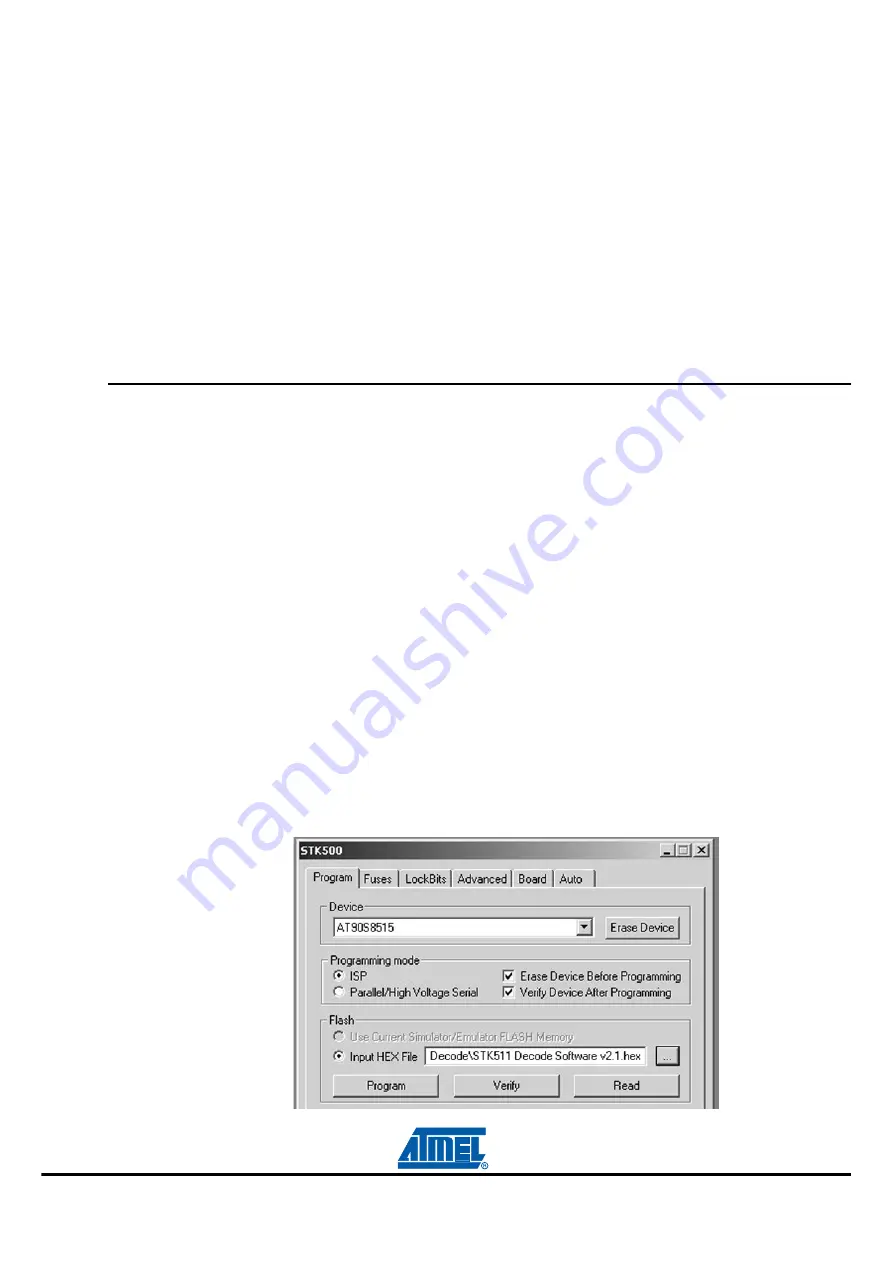
On the Program tab, select AT90S8515 from the Device pull-down menu.
9.
Load the STK511 RX Decode.hex file, included on the Sample Software CD, into the field labeled
Flash Input Hex File and press the Program button (see
Figure 2-1.
Receiver Decode Software


