4.
Hardware User Guide
4.1.
Connectors
This chapter describes the implementation of the relevant connectors and headers on SAM G55 Xplained
Pro and their connection to the ATSAMG55J19. The tables of connections in this chapter also describes
which signals are shared between the headers and on-board functionality.
4.1.1.
Xplained Pro Standard Extension Headers
The SAM G55 Xplained Pro headers EXT1, EXT3, and EXT4 offer access to the I/O of the microcontroller
in order to expand the board by connecting extensions to the board. All these headers comply with the
Xplained Pro standard extension header specification. The headers have a pitch of 2.54mm.
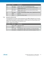
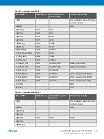
Table 4-1. Extension Header EXT1
Pin on EXT1
SAM G55 pin
SAM G55 Peripheral
Function
Shared Functionality
1 [ID]
-
-
Communication line to ID chip on
extension board.
2 [GND]
-
-
GND
3 [ADC(+)]
PA17
AD0
4 [ADC(-)]
PA18
AD1
5 [GPIO1]
PA26
GPIO
UART0 RTS
6 [GPIO2]
PA25
GPIO
UART0 CTS
7 [PWM(+)]
PA00
TIOA0
8 [PWM(-)]
PA23
TIOA1
9 [IRQ/GPIO]
PA24
WKUP11
10 [SPI_SS_B/GPIO]
PA29
GPIO
11 [TWI_SDA]
PB10
TWD4
12 [TWI_SCL]
PB11
TWCK4
13 [USART_RX]
PA09
USART RXD (URXD0)
14 [USART_TX]
PA10
USART TXD (UTXD0)
15 [SPI_SS_A]
PA11
SPI NPCS0
16 [SPI_MOSI]
PA13
SPI MOSI
EXT3 connector
17 [SPI_MISO]
PA12
SPI MISO
EXT3 connector
18 [SPI_SCK]
PA14
SPI SCK
EXT3 connector
19 [GND]
-
-
GND
20 [VCC]
-
-
VCC
Atmel SAM G55 Xplained Pro [USER GUIDE]
Atmel-42389B-SAM-G55-Xplained-Pro_User Guide-04/2016
11

