2
Atmel AVR2103
8368B-AVR-01/12
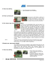
2.1 Board assembling
1. Connect the antennas to both RCBs.
2. Insert two batteries in each of the RCBs.
2.2 Power up the boards
Apply power to both RCBs by switching on
the power switch located on the top side of
the board. The RCBs run a power-on check
and indicate the successful completion by
switching on the second of the three LEDs.
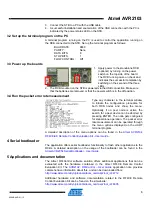
2.3 Run simple range measurement application
Choose one of the RCB128RFA1 RCBs, and press button T1 to
start the simple range measurement application. First, the RCB
initiates a connection and configuration procedure by sending
broadcast frames, and waiting for a response from the second
RCB. After a successful configuration, the RCBs turn on LED-D2
to indicate that status. Afterwards the initiator starts to transmit
data frames immediately. Each data frame transmission is
indicated by blinking the TX status LED-D3. A successful data
frame reception on the second node is indicated by blinking the RX status LED-D4.
The RX status LED stops blinking if no data frames are received, such as when, for
example, the node has left the communication range. Data frame transmission can be
stopped by pressing T1 once more on the node transmitting frames. Moreover the
RCBs can transmit and receive frames simultaneously. Pressing button T1 on both
nodes initiates each node to transmit frames. The three LEDs indicate their respective
functions: LED-D2 a successful configuration, LED-D3 transmission and LED-D4
reception.
NOTE
The node connection and configuration gets lost when the RCBs’ power supply is
switched off. To restart the simple range measurement, power cycle both RCBs
before pressing T1 on one RCB to restart the application.
3 Packet error rate measurement
The pre-flashed performance test application is also configured with packet error rate
(PER) measurement functionality (as defined in IEEE
®
802.15.4), enabling the user to
explore various radio transceiver features, radio transceiver registers, and
performance by tuning with customized configurations. For this application, one
RCB128RFA1 RCB needs to be connected to a PC.
3.1 Board assembling
1. Switch off power from one RCB, or
remove the batteries and connect the
RCB to the STB.
2. Download the patched FT245RL driver
files from the kit website, and follow the
installation guidelines on your PC to
install the USB driver.
config TX RX
status
D2 D3 D4 T1


